I
M7IRDA2003I
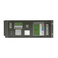
7IRD-A/J/M: Distribution Protection & Control Terminal
© ZIV APLICACIONES Y TECNOLOGÍA, S.L.U. 2020
Table of Contents
1. Description ........................................................................................................... 1-1
1.1 General Overview .................................................................................................. 1-2
1.2 Protection Subsystem Functions ........................................................................... 1-3
1.2.1 Non-Directional Overcurrent Protection 3-Phase and Ground .............................. 1-3
1.2.2 Recloser (7IRD-A/J Models) .................................................................................. 1-3
1.2.3 Breaker Failure Protection ..................................................................................... 1-3
1.2.4 Open Phase Protection .......................................................................................... 1-3
1.2.5 Residual Current Detection (Neutral Unbalance Unit) ........................................... 1-3
1.3 Control Subsystem Functions ................................................................................ 1-4
1.3.1 Local Control and Status Indication of all Bay Elements ....................................... 1-4
1.3.2 Local Recloser Control (7IRD-A/J Models) ............................................................ 1-4
1.3.3 Measurement Presentation.................................................................................... 1-4
1.3.4 Presentation of Local Alarms as Conventional Alarms ......................................... 1-4
1.3.5 Indication of Digital Inputs / Outputs ...................................................................... 1-4
1.3.6 Indication of Auxiliary Inputs / Outputs States and Protection LEDs ..................... 1-4
1.4 Additional Functions .............................................................................................. 1-5
1.5 Model Selection ..................................................................................................... 1-7
2.
Technical Data ..................................................................................................... 2-1
2.1 Power Supply Voltage ........................................................................................... 2-2
2.2 Protection Subsystem ............................................................................................ 2-2
2.2.1 Power Supply Burden ............................................................................................ 2-2
2.2.2 Current Analog Inputs ............................................................................................ 2-2
2.2.3 Measurement Accuracy ......................................................................................... 2-2
2.2.4 Accuracy of Time Measurement ............................................................................ 2-2
2.2.5 Repeatability .......................................................................................................... 2-3
2.2.6 Transient Overreach .............................................................................................. 2-3
2.2.7 Status Contact Inputs ............................................................................................ 2-3
2.2.8 Trip and Close Outputs .......................................................................................... 2-4
2.2.9 Auxiliary Contact Outputs ...................................................................................... 2-4
2.3 Control Subsystem ................................................................................................ 2-5
2.3.1 Power Supply Burden ............................................................................................ 2-5
2.3.2 Current Analog Inputs (Measurement Circuit Board) ............................................ 2-5
2.3.3 Voltage Inputs (Measurement Circuit Board) ........................................................ 2-5
2.3.4 Measurement Accuracy (Measurement Circuit Board) ......................................... 2-5
2.3.5 Accuracy of Time Measurement ............................................................................ 2-5
2.3.6 Status Contact Inputs ............................................................................................ 2-6
2.3.7 Double Contact Outputs (SD1 and SD2) ............................................................... 2-6
2.3.8 Simple Contact Outputs ......................................................................................... 2-6
2.3.9 Transducer Input/Outputs ...................................................................................... 2-6
2.4 Communications Link ............................................................................................ 2-7
3.
Standards and Type Test .................................................................................... 3-1
3.1 Insulation................................................................................................................ 3-2
3.2 Electromagnetic Compatibility ............................................................................... 3-2
3.3 Environmental Test ................................................................................................ 3-3
3.4 Power Supply ......................................................................................................... 3-3
3.5 Mechanical Test ..................................................................................................... 3-3
4.
Physical Architecture .......................................................................................... 4-1
4.1 General .................................................................................................................. 4-2