3
INSTALLATION
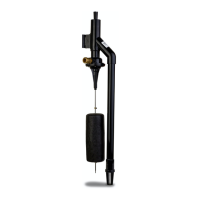
The Home Guard
®
MAX pump can be installed very easily as a standby to an electric sump pump (see sketches).
Sump water is non-potable. To reduce the risk of contamination of the potable water supply, the Home Guard
®
Max must
be installed with a listed backow device suitable for the installation, in accordance with the local plumbing code, such
as a reduced pressure principle backow preventer (RP). Alternately, consult the local plumbing and health codes or the
authority having jurisdiction for guidance on cross-connection and backow protection requirements.
STEP 1: Placement of the Pump in the Pit
Note: If your pit has a cover, it will have to be modied to accommodate the Home Guard
®
Max pump.
1.1) Inspect the pit for debris and clean as necessary.
1.2) Place the pump in the pit, making certain that the inlet tting of the pump is at least 6” above the basement oor or top of the
sump pit. Ensure the pump is clamped securely to the primary pump discharge pipe. Mark the location on the discharge pipe.
IMPORTANT
This pump is to be used as a backup to your primary pump. Make certain that there is no interference between the
two pumps, especially between the oat systems.
STEP 2: Pump Float Stop Adjustment
2.1) With the Home Guard
®
Max pump in the pit, measure the desired oat ON position (this should be a few inches above the
ON level of the existing pump). The pump turns on at a water level of 2” to 3” below the upper oat stop, depending on the
incoming water pressure. Calculate the appropriate oat stop location based on this distance.
2.2) The OFF level is determined by the buoyancy of the oat as well as the incoming water pressure, roughly 6” to 8” below the
ON level. The OFF level must be above the suction screen of the foot valve. Adjusting the lower oat stop will not change
the OFF level of the pump. It is recommended to install the lower stop tight to the bottom of the oat so that it cannot move
on the oat rod.
2.3) Remove the pump from the pit and adjust the oat stops as necessary. Tighten all screws. Be sure to tighten the lower
stop properly so that it will not come off. If the lower stop comes off, the oat can drop off the oat rod, rendering the pump
non-operational and possibly damaging the pump.
2.4) Replace the pump in the pit at the same location on the primary pump discharge pipe as marked earlier (Step 1.2). This will
ensure that the ON and OFF levels are consistent with the calculations.
STEP 3: Installation of the Discharge Piping
3.1) Glue 1½" pipe into the pump discharge connection as shown in the gure on page 5 (reference SK2721).
3.2) Per the Uniform Plumbing Codes and IAPMO PS119, the discharge of the water-powered sump pump should not be
connected to the discharge of the primary sump pump. The discharge piping for water-powered sump pumps must have
an air gap and extend outside of the building, with the end of the pipe between 6 and 24 in. (150 and 610 mm) above the
ground or the ood level of the area receiving the discharge.
3.3) In order for this installation to work properly, a check valve must be installed onto the discharge line. The following Zoeller
check valves are recommended: 30-0100; 30-0101; 30-0102; 30-0103. Some local codes require a union check with ball
valve. Check your local code requirements to ensure that the installation complies.
STEP 4: Installation of the Source Water Piping
Sump water is non-potable. To reduce the risk of contamination of the potable water supply, the Home Guard
®
Max must
be installed with a listed backow device suitable for the installation, in accordance with the local plumbing code, such
as a reduced pressure principle backow preventer (RP). Alternately, consult the local plumbing and health codes or the
authority having jurisdiction for guidance on cross-connection and backow protection requirements.
© Copyright 2015 Zoeller
®
Co. All rights reserved.
 Loading...