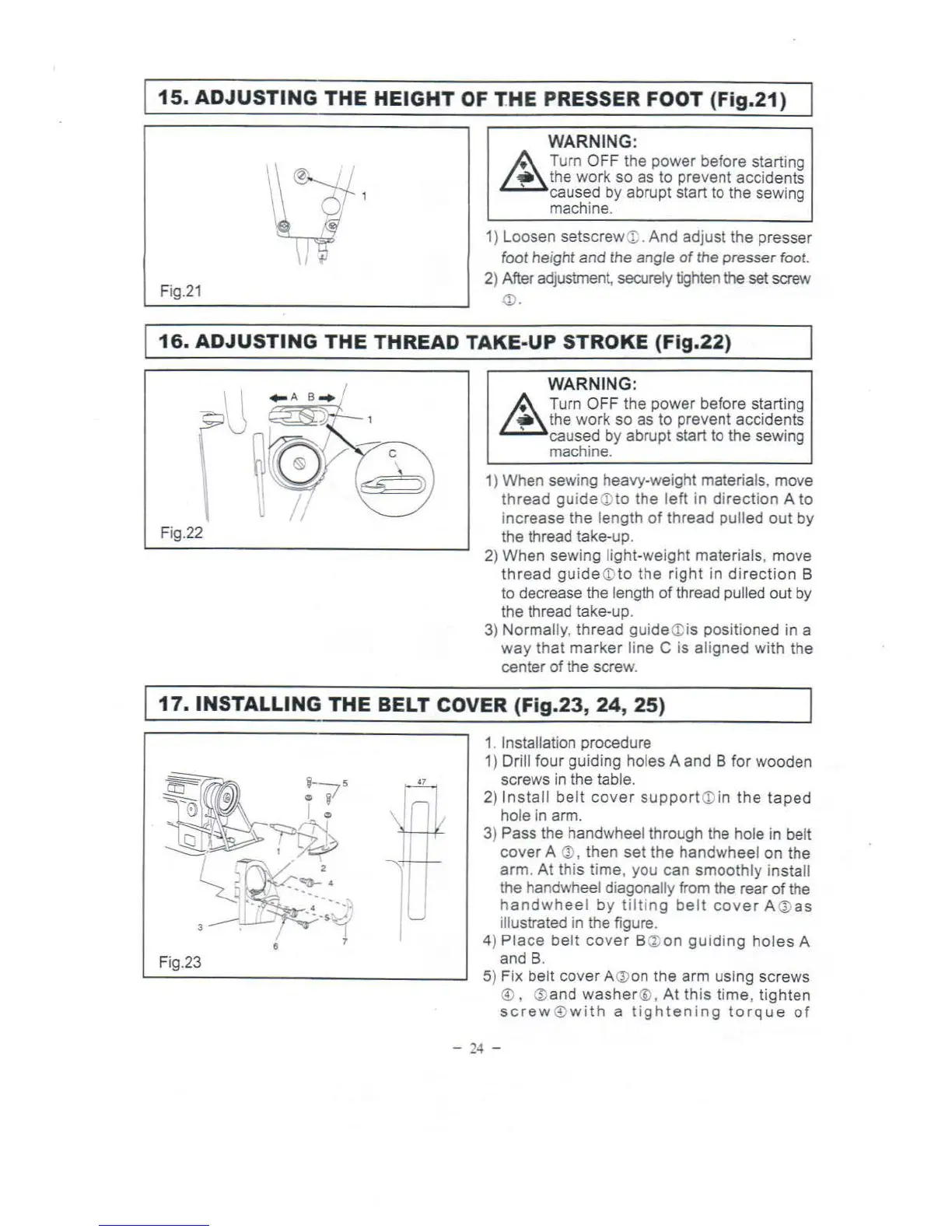
15.
ADJUSTING
THE
HEIGHT
OF
T.HE
PRESSER FOOT (Fig.21)
Fig.21
WARNING:
A Turn OFF the power before starting
~
the
work so as to prevent accidents
' caused by
ab
rupt start
to
the sewing
machine.
1) Loosen setscrew
X;
. And adjust the presser
foot height and the angle
of
the
presser foot.
2) After
ad
justment, securely
tighten
the
set screw
(1).
16.
ADJUSTING
THE
THREAD TAKE-UP STROKE (Fig.22)
Fig.22
WARNING:
A Turn O
FF
the power before starting
~
the
work so as to prevent accidents
' caused by abrupt start
to
the sewing
machi
ne.
1) When sewi
ng
heavy-weight materials, move
thread
guide
CD
to the left in direction A to
increase the length
of
thread pulled out by
the thread take-up.
2) When sewing light-weight materials, move
thread
guide
<D
to the
right
in
direction
B
to
decrease the length
of
thread pulled out
by
the thread take-up.
3)
Normally, thread guide
<D
is positioned in a
way
that marker line C is aligned with the
center of the screw.
17.
INSTALLING
THE
BELT COVER (Fig.23,
24,
25)
fi
I
I
liT
Fig.23
1.
Installation procedure
1)
Drill four guiding holes A and B for wooden
screws
in
the table.
2)
Install
belt
cover
support
CD
in the
taped
hole
in
arm.
3)
Pass the handwheel through the hole
in
belt
cover A
Q),
then set the handwheel on the
arm. At this time, you can smoothly
install
th
e handwheel diagonally
from
the rear
of
the
han
dwhee
l by t
il
ting be
lt
cover
A
Q)
as
illustrated
in the figure.
4)
Place
belt
cover
B
Q;
on guiding
holes
A
and B.
5) Fix belt cover
A
Q)
on the arm using screws
®,
(i)and
washer
@,
At
this time, tighten
screw
®
with
a t i
ghtening
torque
of
-
24
-