EasyManuals Logo
Home>Zotac>Motherboard>IONITX-U series

Zotac IONITX-U series User Manual

Zotac IONITX-U series
46 pages
To Next Page IconTo Next Page
To Previous Page IconTo Previous Page
Page #7 background imageLoading...
Page #7 background image
6
Intel
®
NM10-ITX series Motherboard
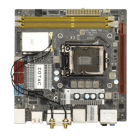
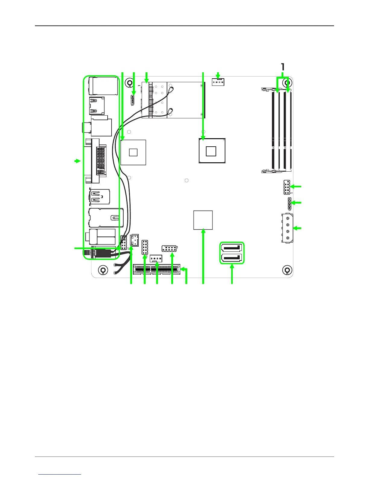
Motherboard Layout
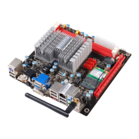
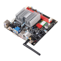
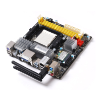
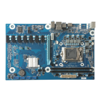
Figure 1 shows the motherboard and Figure 2 shows the back panel connectors.
Figure 1. Board Layout
1. DDRIII SO-DIMM Sockets (DDRIII-1~2)
2. Front Panel Header-FP1
3. Speaker Header-SPK
4. DC-OUT Connector-CN13
5. Serial-ATA (SATA) Connectors (SATA-1~2)
6. Chipset
7. PCI Express x4 Slot (open-ended, single
lane)-PCIE1
8. USB Headers-FP_U1
9. SYS Fan Connector-SYS_FAN
10. COM Header-COM1
11. SPDIF-Out Connector-SPDIF
12. Front Pannel Audio Header-FP_S1
13. Backpanel Connectors
14. GPU
15. Clear CMOS Jumper-JP1
16. Mini PCIE Slot-Mini_PCIEX1
17. Onboard CPU
18. CPU Fan Connector-CPU_FAN
Figure 1
.
.
.
Chipset
DDRIII-2
DDRIII-1
FP_U1
FP1
SATA-1
SATA-2
PCIE1
CPU FAN_
USB3.0
CN13
HDMI
DVI
LAN USB/
SD1
SPDIF
2
3
4
5
6
7
8
11
12
13
SPK
14
15
SYS_FAN
SPDIF
FP_S1
Mini_PCIEX1
2
51
52
CPU
16
17
910
COM1
U_KB1
JP1
GPU
18

Questions and Answers:

Question and Answer IconNeed help?

Do you have a question about the Zotac IONITX-U series and is the answer not in the manual?

Zotac IONITX-U series Specifications

General IconGeneral
BrandZotac
ModelIONITX-U series
CategoryMotherboard
LanguageEnglish

Related product manuals