6
Intel
®
NM10 series Motherboard
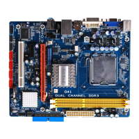
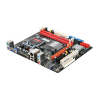
Motherboard Layout
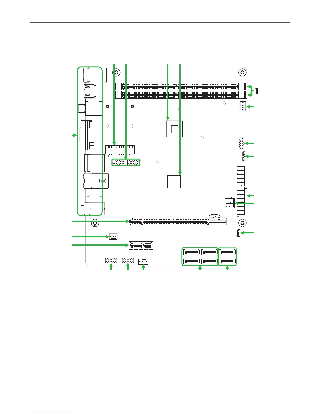
Figure 1 shows the motherboard and Figure 2 shows the back panel connectors.
Figure 1. Board Layout
1. DDRII DIMM Sockets-DDRII1~2
2. CPU Fan Connector-CPU_FAN
3. Front Panel Header-FP1
4. Speaker Header-SPK1
5. 24-pin ATX Power Connector-PW1
6. 4-pin ATX_12V power connector-PW2
7. Clear CMOS Jumper-JP1
8. Serial-ATA Connectors-SATA1~2 (for ordinary
SATA HDDs)
9. Serial-ATA Connectors-SATA3~6 (for creating
SATA RAID)
10. SYS Fan Connector-SYS_FAN
11. COM Header_COM1
12. Front pannel audio Header-FP_S1
13. PCI Express x1 Slot-PCIEX1
14. SPDIF-Out Header-CN6
15. PCI Express x 16 Slot-PCIE2
16. Backpanel connectors
17. Mini PCIE Slot-Mini_PCIEX1
18. USB Headers-FP_U1~FP_U2
19. Onboard CPU
20. Chipset
Figure 1
120
240
121
120
240
121
Chipset
DDRII-1
DDRII-2
PW1
SYS_FAN
FP1
SATA1
SATA2
PCIEX1
CPU FAN_
USB
JP1
PW2
HDMI
VGA
LAN USB/
SD1
KB
USB/
SPDIF
2
3
4
5
6