-i-
A List of Figures
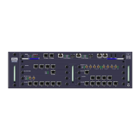
Fig. 3.1-1 Appearance of W140A ..................................................................................................... 3-1
Fig. 3.1-2 W140A Software Structure...............................................................................................3-2
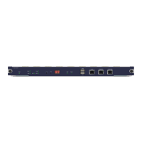
Fig. 3.2-1 W140A Rear Control Panel ..............................................................................................3-2
Fig. 3.3-1 Building Small Wireless LAN..........................................................................................3-3
Fig. 3.3-2 Building Internet Wireless Access Network with AC, Indoor AP and Outdoor Bridge.... 3-4
Fig. 3.3-3 Wireless Bridge Mode ...................................................................................................... 3-5
Fig. 4.1-1 Telnet to W140A ..............................................................................................................5-3
Fig. 5.1-1 Path diagram of WEB configuration ................................................................................6-2
Fig. 5.2-1 Login page for WEB configuration ..................................................................................6-3
Fig. 5.2-2 Alert box for prompting that someone has already logged in for WEB configuration.....6-3
Fig. 5.2-3 Alert box for prompting that the entered user name and password are incorrect .............6-4
Fig. 5.3-1 Home page (basic product information) ........................................................................... 6-5
Fig. 5.3-2 Stations page..................................................................................................................... 6-5
Fig. 5.3-3 Statistics page ...................................................................................................................6-6
Fig. 5.3-4 Load Balance page ...........................................................................................................6-7
Fig. 5.3-5 Submenu for SNMP configuration ................................................................................... 6-8
Fig. 5.3-6 Access mode configuration page of the SNMP module ...................................................6-8
Fig. 5.3-7 Access host configuration page of the SNMP module .....................................................6-9
Fig. 5.3-8 Community configuration page of the SNMP module ................................................... 6-10
Fig. 5.3-9 System information configuration page of the SNMP module.......................................6-10
Fig. 5.3-10 Trap configuration page of the SNMP module............................................................. 6-11
Fig. 5.3-11 Trap sink configuration page of the SNMP module .....................................................6-12
Fig. 5.3-12 Submenu of security configuration...............................................................................6-12
 Loading...