Touchscreen User Manual – Issue 1
Zytronic X-Y Controller (Serial and USB) 16
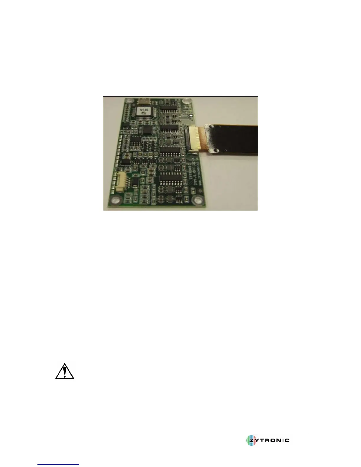
• The flexi tail connectors will insert approx 3mm to 4mm into the body of the on board PCB
ZIF connector.
• With the flexi tail inserted into the ZIF connector, now push down the locking bar located
towards to back of the ZIF connector body. When the connector is fully locked in place the
locking bar should be completely horizontal with the body of the connector, as shown in
Figure 11. It is important that the connector is fully locked in place to prevent the flexi tail
slipping out of the ZIF connector.
Figure 11: Push down locking bar on ZIF connector to lock flexi tail in place
The sensor is now connected to the controller PCB card.
Points to note when routing the flexi tail to the controller:
• Ensure the flexi tail is routed as far away as possible away from sources of noise (i.e.
transformers, AC sources, motors, backlight inverters, etc) to minimise interference with the
controller PCB card and its operation.
• Ensure the sensor flexi tail is not severely clamped between sharp edges of metal work. If so
apply a thin gasket to the area in question to prevent the tail from being damaged, as shown in
Figure 12.
• Ensure the flexi tail routes directly to the sensor with minimum bends, ideally none at all.
• Although the flexi tail is fully shielded and immune to a certain extent to metal work, it is
worth where ever possible to avoid direct contact with metal work. This can be achieved by
insulating the tail with foam tape when direct metal contact with the tail is apparent.
• Do not bend the flexi tail to less than a radius of 2.5mm. The flexi tail can be damaged and
the touchscreen may not operate correctly if the flexi tail is severely creased.
WARNING: Do not bend the flexi tail to less than a radius of 2.5mm.