MES-3528 User’s Guide
33
CHAPTER 3
Hardware Overview
This chapter describes the front panel and rear panel of the Switch and shows you
how to make the hardware connections.
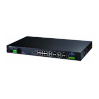
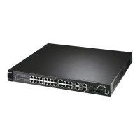
3.1 Front Panel
The following figure shows the front panel of the Switch.
Figure 8 Front Panel
The following table describes the port labels on the front panel.
Ethernet Ports
Dual Personality Interfaces
Console Port
LEDs
ALARM slot
Power Connection
Table 1 Front Panel Connections
LABEL DESCRIPTION
Power
Connection
Connect an appropriate power supply to this port.
24 10/100
Mbps RJ-45
Ethernet
Ports
Connect these ports to a computer, a hub, an Ethernet switch or router.
 Loading...