8
Installation
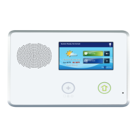
Control Panel Mounting Plate
The Control Panel should be mounted on the wall in an easy
location for the subscriber to operate the system.
1. Remove the locking screw from the top of the Control Panel case and
remove the mounting plate.
2. Use the mounting plate as a template to mark the wall for the wiring
cutout slot. Use a drywall saw to cut the slot. If using the optional
Model 2GIG-GSMx GSM module with the external Model 2GIG-ANT1X
or Model 2GIG-ANT2X antenna, remove the plastic knockout labeled
“EXTERNAL ANTENNA” on the mounting plate. Mark and cut a slot in the
drywall for the external antenna.
3. Attach the mounting plate to the wall using three screws.
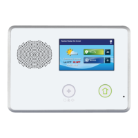
Wireless Sensors
Each wireless sensor needs to be installed at its desired location.
1. Following the instructions included with each wireless sensor, install each
sensor at its desired location.
2. Use the Installation Log to document each sensor’s ID number and
location.
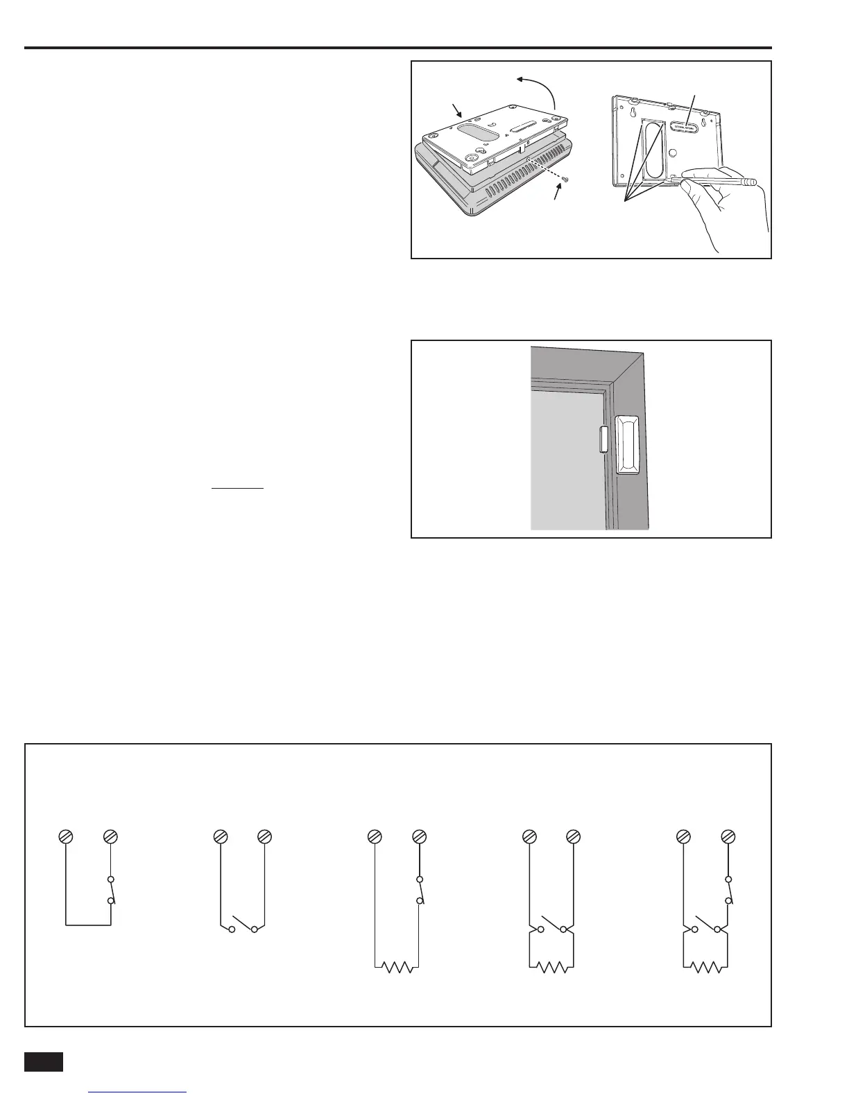
Hardwired Loops
Hardwired loops can be programmed either normally open (N/O)
or normally closed (N/C). End-of-line resistors (EOLR) can also be
used to supervise the loops.
Only contacts should be used with the hardwired loops. The Control
Panel does not support powering external devices (PIR’s, etc.).
✓ NOTE: HARDWIRED LOOPS CANNOT BE USED FOR A CO
OR FIRE SENSOR LOOP.
1. If either of the two hardwired loops are going to be used, install the contacts
and route the loop wire to the Control Panel’s wall cutout.
2. If end-of-line supervision is required for the loop, install a 2.2K ohm resistor
(not supplied) as shown in the loop illustration.
REMOVE CASE SCREW
AND MOUNTING PLATE
MOUNTING
PLATE
USE MOUNTING PLATE
AS A TEMPLATE TO
MARK WIRE CUTOUT
HOLE IN DRYWALL
IF USING EXTERNAL
GSM ANTENNA, REMOVE
KNOCKOUT
MOUNT
PLATE
WITH 3
SCREWS
Figure 7. Wall Mounting Template
Figure 8. Typical Door Sensor Installation
HARDWIRE LOOP WIRING EXAMPLES
N.C.
N.O.
2.2K EOLR
HARDWIRE
LOOP 1 OR 2
GROUND
MIXED
EOL LOOP
N.O.
2.2K EOLR
HARDWIRE
LOOP 1 OR 2
GROUND
N.O.
EOL LOOP
2.2K EOLR
N.C.
HARDWIRE
LOOP 1 OR 2
GROUND
N.C.
EOL LOOP
N.O.
HARDWIRE
LOOP 1 OR 2
GROUND
N.O.
LOOP
N.C.
HARDWIRE
LOOP 1 OR 2
GROUND
N.C.
LOOP
HARDWIRE LOOPS NEED TO BE
PROGRAMMED FOR CONTACT TYPE
Figure 9. Hardwired Loop Wiring

 Loading...