2
Introduction
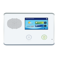
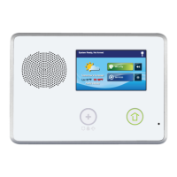
The Go!Control Security System represents a signifi cant
advancement in fully supervised wireless security systems. The
security system Control Panel incorporates many advanced
and sophisticated features. The system can be expanded and
customized to fi t the installation’s specifi c needs.
Designed to meet or exceed the requirements for ETL Listed
residential security installations, the system also conforms to the
Security Industry Association’s Control Panel Standard ANSI/SIA
CP-01-2010.
✓ NOTE: Failure to install the Control Panel and accessories in
accordance with ETL requirements listed in this manual voids
the ETL listing mark assigned by Intertek.
Many insurance companies offer discounts on homeowners’ and
renters’ policies when a security system is installed. Discount
credits vary with different companies and generally increase in
savings with an increase in the level of protection. Inform the user
to ask their insurance agent about savings available.
This security system is ETL Listed. For an ETL smoke alarm
system, there must be at least one smoke detector programmed
into the Control Panel to meet National Fire Protection Association
(NFPA) Rule 72-Chapter 2, and UL 217 requirements. Many
insurance companies require meeting these requirements to
qualify for a discount. For an ETL smoke alarm system, use only
approved model smoke detectors with this Control Panel.
✓ NOTE: Some cities and municipalities may require an alarm
system permit. Check with the local authorities before installing
this system.
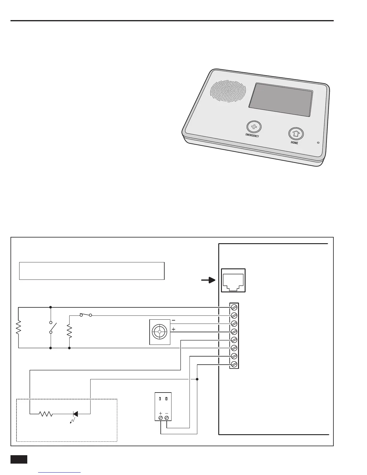
NORMALLY CLOSED
CONTACT
NORMALLY
OPEN
CONTACT
2.2 K
END-OF-LINE RESISTORS ARE
OPTIONAL ON HARDWIRE LOOPS
2.2 K
HARDWIRE LOOPS
CAN BE PROGRAMMED
AS NORMALLY OPEN OR CLOSED
SUPERVISED BELL OUTPUT
6-12 VDC @ 120 mA MAXIMUM
TELEPHONE LINE
FROM RJ31X
TELEPHONE JACK
PIEZO
SIREN
120 VAC 60 HZ
PLUG-IN 14 VDC
1.7 AMP SWITCHING
POWER SUPPLY
1 K LED
OPEN COLLECTOR OUTPUT
250 mA @ 16 VDC MAXIMUM
EXAMPLE HOOKUP SHOWING AN ARMED LED,
THE OPEN COLLECTOR OUTPUT CAN BE PROGRAMMED
TO ACTIVATE DURING VARIOUS CONDITIONS
UL NOTE: WIRING FOR ALL WIRED SENSORS AND ANNUNCIATORS MUST USE
UL LISTED LOW VOLTAGE CL2X OR BETTER GRADE WIRE. SENSOR AND DISPLAY
VOLTAGES MUST COMPLY WITH CLASS 2 LOW VOLTAGE REQUIREMENTS.
OBSERVE
POLARITY WHEN
CONNECTING THE
POWER SUPPLY !!!
CONTROL PANEL
TELEPHONE
JACK
8 - HARDWIRE LOOP 2
7 - HARDWIRE LOOP 1
6 - BELL (-)
5 - BELL (+)
4 - OPEN COLLECTOR OUTPUT
3 - GROUND
2 - 14 VDC POWER INPUT (-)
1 - 14 VDC POWER INPUT (+)
NOTE: TERMINAL 1 WILL ONLY
PROVIDE DC POWER WHEN
THE CONTROL PANEL'S
POWER SUPPLY IS CONNECTED
TO AN AC POWER SOURCE
ALL OUTPUT
VOLTAGES
ARE CLASS 2
REFERENCE ONLY - REFER TO ADDENDUM 230373 FOR PROPER
INSTALLATION AND WIRING DIAGRAM
Figure 2. Control Panel Wiring Diagram
2GIG-CNTRL2
(2GIG-CP2)

 Loading...