MSDP Configuration Examples 485
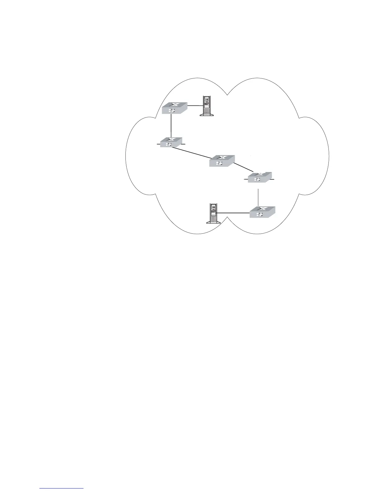
Network diagram
Figure 117 Network diagram for Anycast RP configuration
Configuration procedure
1 Configure SwitchB:
# Configure VLAN
<SwitchB> system-view
System View: return to User View with Ctrl+Z.
[SwitchB] vlan 10
[SwitchB-vlan10] port ethernet1/1/2
[SwitchB-vlan10] quit
[SwitchB] vlan 20
[SwitchB-vlan20] port ethernet1/1/3
[SwitchB-vlan20] quit
# Enable multicast.
[SwitchB] multicast routing-enable
# Configure the IP address of interface loopback0.
[SwitchB] interface loopback0
[SwitchB-LoopBack0] ip address 10.10.1.1 255.255.255.255
[SwitchB-LoopBack0] quit
# Configure the IP address of interface loopback10 and enable IGMP and PIM-SM.
[SwitchB] interface loopback10
[SwitchB-LoopBack10] ip address 10.1.1.1 255.255.255.255
[SwitchB-LoopBack10] igmp enable
SRC A
SwitchE
Loopback0
10.10.1.1
Loopback10
10.1.1.1
Vlan-interface20
10.10.3.1/24
Loopback10: Anycast RP address
10.1.1.1
Loopback0
:
MSDP peer address
& Originating-RP
SwitchB
SwitchD
SwitchA
SRC B
SwitchC
Vlan-interface20
10.21.2.1/24
Loopback0
10.21.1.1
Loopback10
10.1.1.1
Vlan-interface10
10.21.3.1/24
Vlan-interface10
10.10.2.1/24
E1/1/3
E1/1/2
E1/1/3
E1/1/2
SRC A
SwitchE
PIM-SM domain
Loopback0
10.10.1.1
Loopback10
10.1.1.1
Vlan-interface20
10.10.3.1/24
Loopback10: Anycast RP address
10.1.1.1
Loopback0
:
MSDP peer address
& Originating-RP
SwitchB
SwitchD
SwitchA
SRC B
SwitchC
Vlan-interface20
10.21.2.1/24
Loopback0
10.21.1.1
Loopback10
10.1.1.1
Vlan-interface10
10.21.3.1/24
Vlan-interface10
10.10.2.1/24
E1/1/3
E1/1/2
E1/1/3
E1/1/2