4-4
WDS Point-to-Multipoint Configuration Example
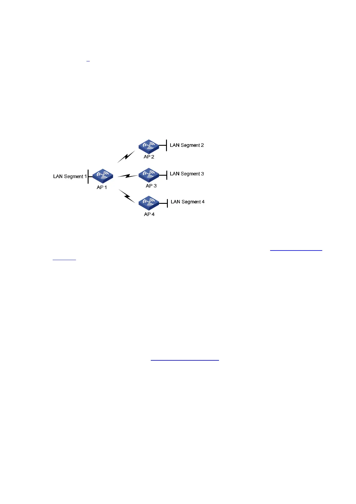
Network requirements
As shown in 0, it is required that AP 1 establish a WDS link with AP 2, AP 3, and AP 4 respectively.
The WDS configuration is the same as the normal WLAN WDS configuration. Note the following when
configuring WDS:
z Configure a neighbor MAC address for each radio interface (otherwise, WDS links may be
established between AP 2, AP 3 and AP 4).
z Set the maximum number of WDS links allowed. The default value is 2. It should be set to 3 for AP
1 in this example.
Figure 4-7 Network diagram for WDS configuration
Configuration procedure
WDS configuration is the same as normal WLAN WDS configuration. Refer to WDS Configuration
Example
for details.
Configuration verfication
Display WDS link status:
z It is displayed on the WDS link status page of AP 1 (which you can enter by selecting Summary >
WDS from the navigation tree) that AP 1 has established a WDS link with AP 2, AP 3 and AP 4
respectively.
z It is displayed on the WDS link status page of AP 2, AP 3 and AP 4 (which you can enter by
selecting Summary > WDS) that AP 2, AP 3 and AP 4 have respectively established a WDS link
with AP 1.
Configuration guidelines
When satisfied with the configuration Save Configuration to File to ensure it is not lost when the Access
Point restarts.