12 CHAPTER 1: INTRODUCING THE BASELINE SWITCH
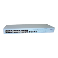
Ports 25 and 26 are not configured to provide Power
over Ethernet.
The two SFP ports support fiber Gigabit Ethernet
short-wave (SX) and long-wave (LX) SFP transceivers
in any combination. This offers you the flexibility of
using SFP transceivers to provide connectivity
between the Switch and remote 1000 Mbps work
-
groups or to create a high-capacity aggregated link
backbone connection.
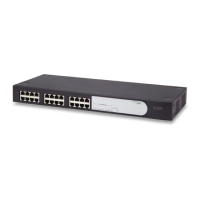
SFP ports are numbered 25 and 26 on the Switch.
When an SFP port is active, it has priority over the
10/100/1000 port of the same number. The corre
-
sponding 10/100/1000 port is disabled when an SFP
transceiver is plugged in.
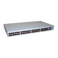
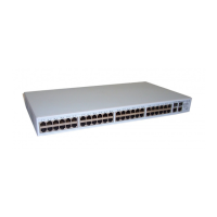
(6) Power LED
The Power LED shows the power status of the Switch.
(7) Duplex LEDs
The second and fourth (bottom) row of Status LEDs,
which are colored yellow, show the duplex status of
the related ports.
(8) Self-Adhesive Pads
The unit is supplied with four self-adhesive rubber
pads.
Do not apply the pads if you intend to rack-mount
the unit.
If the unit is to be part of a free-standing stack, apply
the pads to each marked corner area on the under
-
side of the unit. Place the unit on top of the lower
unit, ensuring that the pads locate with the recesses
of the lower unit.
Rear Panel
(9) Power Supply
The Switch automatically adjusts to the supply volt-
age. Only use the power cord that is supplied with
the unit.
(10) Recovery Button
Use the Recovery button on the rear panel to reset
the Switch to its factory defaults. For more informa
-
Status Meaning
Green The unit is powered on and ready for use
Off The unit is not receiving power:
■ Verify that the power cord is connected cor-
rectly
■ If the unit still does not operate, contact your
3Com network supplier
Flashing
Green
■ Power-on self-test is in progress
Yellow ■ Power-on self-test or loopback test failed.
Switch is in fail-safe mode.
Status Meaning
Off No link, link is not yet negotiated, or the port is
operating in half-duplex mode
Yellow The port is operating in full-duplex mode