23
Machine Set-Up
The following instructions are presented in the
order recommended for setting up and installing the
case sealer, as well as for learning the operating
functions and adjustments. Following them step by
step will result in your thorough understanding of
the machine and an installation in your production
line that best utilizes the many features built into
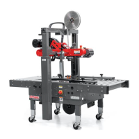
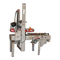
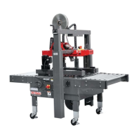
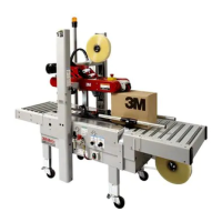
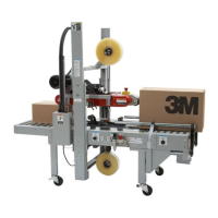
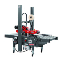
the case sealer. Refer to Figure 7-13 to identify the
various components of the case sealer.
1. Install the upper tape drum bracket on the top
crossbar as shown in Figure 7-7A.
2. The column guards, shown in Figure 7-7 have
been installed upside down for shipping.
Remove and retain the screws and washers
holding the guards on the columns for reinstallation
after the Bumper Supports have been mounted
(see Column Bumper Installation in the Installation
and Set-Up Section and Special Set-Up Proce-
dures Section / Figure 7-7 and Section 13).
After the Bumpers have been installed, the Column
Guards must be repositioned (rotated 180° and
re-installed - Figure 7-7) for safe operation of the
machine. Replace existing screws and washers to
secure the guards in place.
3. Cut cable ties securing upper assembly to machine
bed on each side.
4. Pneumatic connection.
a. Read and remove safety tag from pneumatic
"On/Off" valve.
b. Connect the main air supply line to the inlet
side of the on/off valve using the barbed
fi tting and hose clamp provided
(See Figure 7-7B).
The customer supplied air hose (8mm [5/16 inch]
must be clamped tightly to the barbed fi tting.
If another type of connector is desired, the
barbed fi tting can be removed and replaced with
the desired 1/4-18 NPT threaded connector.
Always turn the air valve "Off" when the air
supply line is being connected or disconnected.
5. Turn the air supply on by turning the air on/off
valve to SUP (On).
6. Raise and latch upper drive assembly in full "Up"
position.
Note – A precision regulator is used to balance the
upper drive assembly. Due to the self relieving
feature of this regulator a small amount of air
will continually vent to the atmosphere. This
is normal and amounts to approximately
3 litre/min. [0.1 SCFM].
Important – Use care when working with
compressed air.
The case sealer requires a 5 bar gauge pressure
110 litre/min [70 PSIG], @21°C, 1.01 bar [3.75 SCFM]
compressed air supply. As shown in Figure 7-14,
an on/off valve, pressure regulator, and fi lter are
provided to service the air supply.
Note – Read "Operation – Mechanical Latch"
before raising and latching upper drive
assembly.
• To reduce the risk associated with
impact hazards:
− Always use appropriate supporting
means when working under the upper
drive assembly
7-INSTALLATION (continued)
• To reduce the risk associated with
mechanical and electrical hazards:
− Allow only properly trained and
qualifi ed personnel to operate and
service this equipment.
7000r-7000r3 Pro - NA
2014 June
WARNING
WARNING
 Loading...