3M™ Multi-Touch Chassis Display User Guide 45
3M Touch Systems, Inc. Proprietary Information – TSD-39373B
Guidelines for Calibrate Command
Here are several guidelines for using the Calibrate commands:
• The controller uses the data immediately before liftoff to register a calibration touch.
Therefore, you can touch the coordinate target, hold for a few seconds, and then lift
off. Instructing users to touch this way results in a more accurate calibration.
• The controller stores the data in non-volatile memory (NOVRAM). Therefore, you
do not have to calibrate the sensor each time you power on the system. You should,
however, recalibrate the touch sensor any time the video display changes size or
resolution.
• You can cancel calibration at any time during this sequence by issuing a Reset
command.
Determining Target Areas
The default calibration targets (points) are located 12.5% (1/8) inward from the corners of
the video image. For example, the resolution of your Windows-based display is 1680 x
1050. The Calibrate Extended command calculates the amount to move inward as
follows:
• Amount to move inward in the X direction: 1680 x 1/8 = 210
• Amount to move inward in the Y direction: 1050 x 1/8 = 131
The Calibrate Extended command then positions the first calibration target inward from
the lower left corner (0,1049) and the second calibration target inward from the upper
right corner (1679,0). The following illustration shows how the calibration targets are
calculated for a Windows-based system. Your operating system may be different.
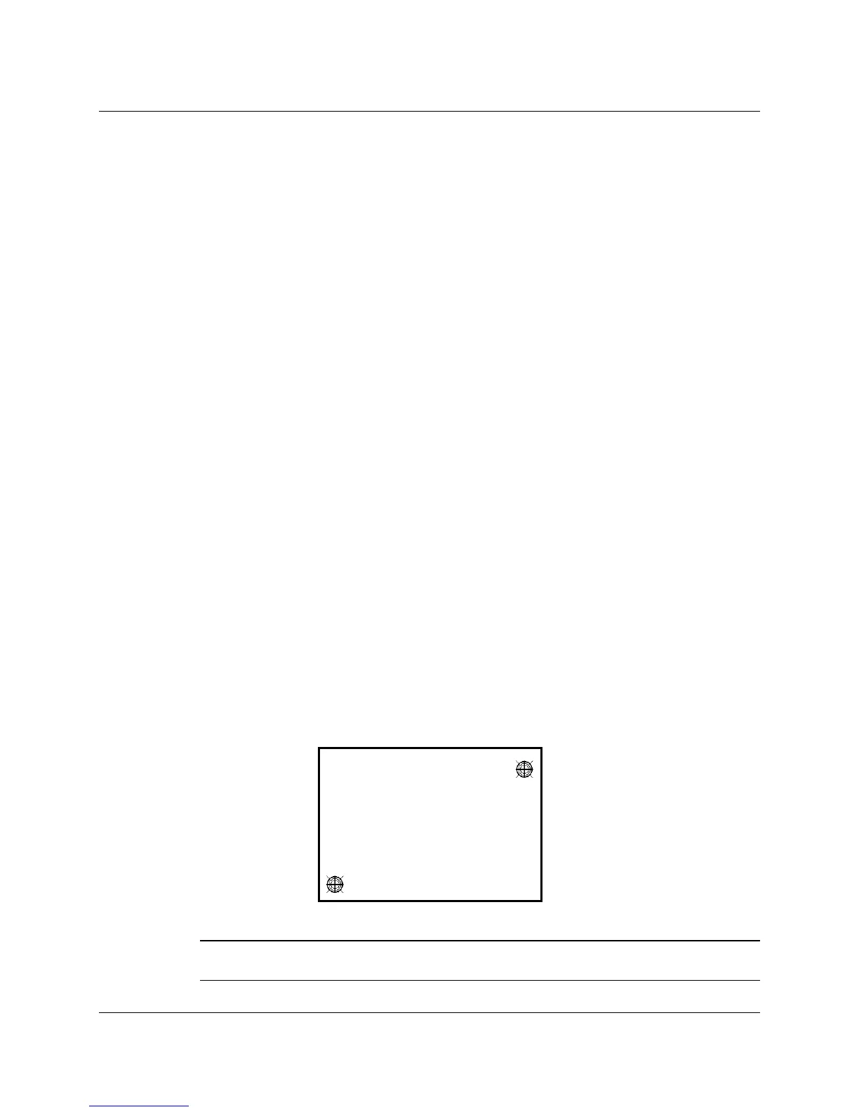
The illustration below shows the coordinates of the calibration targets and display
corners. The corners show the video coordinates in parentheses and the touch screen
coordinates in brackets. Note that the touch screen coordinates for the serial interface
have their origin in the lower-left corner.
Note: Other screen resolutions will scale proportionally. The touch coordinates will not
change.
(0, 1049) [0, 0] (1679, 1049) [16383, 0]
Upper Right Calibration Target
X = 1679 – (1680 x 1/8) = 1679 – 210 = 1469
Y = 0 + (1050 x 1/8) = 0 + 131 = 131
Lower Left Calibration Target
X = 0 + (1680 x 1/8) = 0 + 210 = 210
Y = 1049 - (1050 x 1/8) = 1049 - 131 = 918
(0, 0) [0, 16383]
(1679, 0) [16383, 16383]
(210, 918)
(1469, 131)