2
GZXO
USER INSTRUCTIONS
Please read these user instructions in conjunction with other relevant user instructions
and reference leaflets where you will find information on approved combinations,
spare parts and accessories.
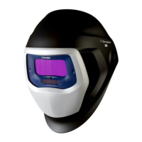
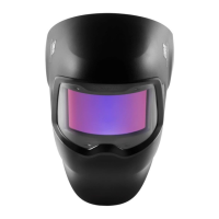
SYSTEM DESCRIPTION
The product helps protect the wearer's eyes and face. It gives permanent protection
from sparks/spatter, UV- and IR radiation resulting from certain arc/gas welding
processes (shade 12 equivalent regardless of whether the filter is in the light or dark
state or whether the auto-darkening function is operational).
WARNING!
Proper selection, training, use and appropriate maintenance are essential in order for
the product to help protect the wearer. Failure to follow all instructions on the use of
these personal protection products and/or failure to properly wear the complete
product during all periods of exposure may adversely affect the wearer's health, lead
to severe or life threatening illness or permanent disability. For suitability and proper
use follow local regulations and refer to all information supplied.
^
Particular attention should be given to warning statements where indicated.
APPROVALS
The PPE is CE marked and in conformity with the European PPE Regulation,
directives and harmonized European Standards as listed in fig H:1 , which also
contains information about the Notified Body that have issued the EU
type-Examination certificate for the PPE (Module B) and when applicable, the Notified
Body responsible for the surveillance of the quality system of the manufacturing of the
PPE (Module D). The EU type-examination Certificates and Declaration of Conformity
are available at www.3M.com/welding/certs.
LIMITATIONS OF USE
^
Only use with original 3M branded spare parts and accessories listed in these
user instructions and within the usage conditions given in the technical specifications.
^
The use of substitute components, decals, paint or other modifications not
specified in these user instructions might seriously impair protection and may
invalidate claims under the warranty or cause the product to be noncompliant with
protection classifications and approvals.
^
Eye protectors worn over standard ophthalmic spectacles may transmit impacts
thus creating a hazard to the wearer.
^
Use of this product in applications outside its intended use, such as laser
welding/cutting, may result in permanent eye injury and vision loss.
^
Severe burn injuries may result if these welding helmets are used for heavy-duty
overhead welding applications where there is a potential for falling molten metal.
^
Should the product fail to switch to the dark state in response to an arc, stop
welding immediately and inspect the welding filter as described in these instructions.
Continued use of a welding filter that fails to switch to the dark state may cause
temporary vision loss. If the problem cannot be identified and corrected, do not use
the welding filter, contact your supervisor, distributor or 3M for assistance.
^
Materials which may come into contact with the wearer’s skin are not known to
cause allergic reactions to the majority of individuals. These products do not contain
components made from natural rubber latex.
^
Flashing light sources (i.e. flash tube strobe lights, safety warning lights, etc.) can
trigger the welding filter causing it to flash even when no welding is occurring. This is
inherent with all auto-darkening filter technology. This interference can occur from long
distances and/or from reflected light. Welding areas must be shielded from such
interference, or replace lights with an LED strobe light.
MARKINGS
Welding filter:3/8-12 3M 1/1/1/2/379
3 / 8-12 3M 1 /1 / 1 / 2 / EN379 CE
Light shade
Dark shade(s)
Manufacturer identification
Optical class.
Diffusion of light class
Variations in Luminous transmittance class
Angle dependency class
Certification mark or number of standard
Note! The above is an example. Valid classification is marked on the welding
filter.
Welding helmet: 3M EN 175B
Outer protection plate: 3M 1 BT*
Inner cover plate: 3M 1 S
3M= Manufacturer
1= Optical class
S= Increased robustness
B= Resistance to high speed particles at medium energy impact (120 m/s.)
BT= Resistance to high speed particles at medium energy impact (120 m/s.)
at extremes of temperatures (-5°C and +55°C)
If the symbols of the impact marking (F,B) are not common to both the outer
protection plate and the helmet shell, the lower protection level shall be
assigned to the complete protection equipment
*EN 166: if protection against high speed particles at extremes of
temperature is required then the selected eye-protector should be marked
with the letter T immediately after the impact letter, i.e. FT, BT or AT. If the
impact letter is not followed by the letter T then the eye protector shall only be
used against high speed particles at room temperature
Additional markings on the product refer to other standards.
Z
Read instructions before use
Serial no = Year, week of manufacturing
R
= Year
Q
= Month
O = Shall be disposed of as electrical and electronic waste
PREPARATION FOR USE
Carefully check that the product is complete (see fig A:1), undamaged and
correctly assembled, any damaged or defective parts must be replaced
before each use. Check for cracks in the helmet and look for light leaks.
^ Cracked, pitted or scratched filter glass or protection plates reduce vision
and can seriously impair protection. All damaged components should be
replaced immediately. Remove any protective film before use and ensure
that your welding filter is equipped with an outer/ inner protection/cover plate.
^ The welding helmet is heat resistant but can catch fire or melt in contact
with open flames or very hot surfaces. Keep the shield clean to minimize this
risk.
OPERATING INSTRUCTIONS
Adjust the welding helmet according to your individual requirements to reach
the highest comfort and protection (see fig B:1- B:3). Shade number may be
chosen according to table (see fig G:1). To activate the welding filter, press
the SHADE/# button. The welding filter automatically turns OFF after 1 hour
of inactivity.
SHADE
To select another Shade Number, press the SHADE/# button repeatedly.
SENSITIVITY SETTING
The sensitivity setting of the weld arc detection system can be adjusted to
accommodate a variety of welding methods and workplace conditions. In
order to see the current sensitivity setting momentarily press the Sensitivity
button. To select another setting press the Sensitivity button repeatedly until
the indicator shows the desired setting.
Position 1 Least sensitive setting. Used if there is interference from other
welders arcs in the vicinity.
Position 2 Normal position. Used for most types of welding indoors and
outdoors.
Position 3 Position for welding with low current or with stable welding arcs.
(eg TIG welding).
Position 4 Suitable for very low current welding, use of inverter type TIG
welding machines.
DELAY
The delay function should be used to set the recovery delay of the welding
filter from dark to light according to welding method and current
Position - Short opening time
Position I Normal opening time
Position + Long opening time
IN USE
The batteries should be replaced when the low battery indicator flashes or
indicators do not flash when the buttons are pressed.
The sensors (see fig A:2) on the welding filter must be kept clean and
uncovered at all times for correct function.
O-AICC17-MAC10-DV-2563-0653-6_Iss1.pdf 5 30/10/2018 12:31
 Loading...