9 10
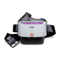
Fig. 12 – 3M™ Backpack BPK-01
BREATHING TUBE
The 3M™ Versao™ Powered Air Purifying Respirator TR-600 is approved for use with 3M™ Versao™ Breathing Tubes.
Select an approved breathing tube that is appropriate for the work conditions.
1. Insert the end of the breathing tube with the bayonet tting (two small prongs) into the parallel slots in the air outlet of the
motor/blower (Fig. 13).
2. Twist the breathing tube 1/4 turn to the right to lock it into place.
3. Refer to the User Instructions for the headgear to be used for procedures to connect the breathing tube to the headgear.
Fig. 13 – Installing breathing tube
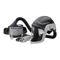
HEADGEAR
The 3M™ Versao™ Powered Air Purifying Respirator TR-600 is approved for use with many 3M headgear options. Refer to
the headgear User Instructions for information on attaching and donning the headgear to be used, and to determine assigned
protection factor (APF) for the complete respiratory protection system. Consult 3M Technical Data Bulletin #175 for additional
information on APFs and supporting test data.
OPERATING INSTRUCTIONS
On, Off and Airow Selection
Power 3M™ Versao™ Powered Air Purifying Respirator TR-600 on:
• Press and hold the smaller, blue power button (Fig. 14, #1) for 1 second. The unit will turn on and perform a self-diagnostic.
The ow level, lter loading and battery charge indictors will blink, and the auditory and vibratory alarm will sound. Battery
indicator (Fig. 14, #4) will show current charge status of the battery pack. Filter indicator will show remaining capacity of
the lter (Fig. 14, #5). Continuous blinking and/or sounding of any alarm indicates a fault condition that must be
corrected prior to use of the respirator system. If auditory alarm or visual indicators do not activate at start-up, do
not use system. Remove from service and see your supervisor.
Select airow:
• There are three user selectable airow settings – standard, medium, and high ow. The motor/blower will start at the
standard ow setting. Pressing and holding the larger blue ow control button (Fig. 14, #2) for 1 second will cycle the
motor/blower to the next of three ow settings. One beep and ow LED on the ow setting indicator (Fig. 14, #3) indicates
standard ow, two beeps and two ow LEDs indicate medium ow, three beeps and three ow LEDs indicate high ow.
Pressing the ow control button cycles back to the standard ow setting.
Power 3M™ Versao™ Powered Air Purifying Respirator TR-600 off:
• Press and hold blue power button for 2 seconds (Fig. 14, #1).
1
2
3
4
5
6
1. On/Off button
2. Flow control button
3. Flow level/alarm indicator
4. Battery charge status level/
alarm indicator
5. Filter loading/alarm indicator
6. Tight-tting mode indicator
(future option)
Fig. 14 – Motor/blower User Interface
Display Sleep Mode
To conserve battery power, the display will go into ‘sleep mode’ after 30 seconds from the last button press. The ow speed
indicator will periodically blink with the current ow setting (Fig. 14, #3). To wake up the display, momentarily press any
display button.
Battery Charge Status Indicator and Low Battery Alarm
The battery level/alarm indicator (Fig. 14, #4) displays the remaining battery charge status. This charge status indicator
mirrors the charge status indicator on the battery. The number of bars illuminated indicates approximate battery pack
charge status remaining: 5 bars = 80-100%, 4 bars = 60-80%, 3 bars = 40-60%, 2 bars = 20-40%, 1 bar = < 20%,
1 bar ashing = < 10%. The charge status indicator is based on the original charge capacity. It does not recalibrate as the
battery ages, and the number of bars illuminated with a fully charged battery will decrease as the battery naturally loses
capacity. This is a safety feature so that throughout the life of the battery the number of charge status bars lit consistently
indicates approximate run time remaining (with a given system setup and lter loading). When the low battery alarm
sounds, users must immediately exit the hazardous area and replace the battery.
Filter Load Indicator and Low Flow Alarm
The lter loading indicator (Fig. 14, #5) monitors the pressure drop in the system. Increase loading of contaminants on the
lter is indicated by the progressive extinguishing of LEDs in the lter loading indicator. As the pressure drop increases the
motor/blower fan speed increases to compensate. When the fan is no longer able to compensate and provide adequate
airow the motor/blower will alarm. A low ow alarm is indicated by the bottom LED of the lter loading indicator ashing
RED. When the low ow alarm sounds, users must immediately exit the hazardous area and replace the
lter/cartridge and/or the prelter/spark arrestor.
INSPECTION
W WARNING
Failure to follow these User Instructions may reduce respirator performance, overexpose you to contaminants,
and may result in injury, sickness, or death.
a. Do not use with parts or accessories other than those manufactured by 3M as described in these User Instructions or
on the NIOSH approval label for this respirator.
b. The 3M™ Versao™ Powered Air Purifying Respirator TR-600 assembly is one component of an approved respiratory
protection system. Always read and follow all User Instructions supplied with your 3M headgear and other system
components in order to ensure correct system operation.
Before each entry into a contaminated area, the following inspection must be performed to help ensure proper function of
the respirator system. Respirator systems are intended to help reduce exposures to certain contaminants and should always
be handled with care and fully inspected prior to use. Refer to the specic assembly subsection of these User Instructions for
proper assembly procedures.
1. PAPR system:
Closely inspect the entire PAPR system including the motor/blower, cover, lter/cartridge, breathing tube, battery, belt and
headgear. Pay particular attention to component connection points for wear or damage. If parts are missing or damaged,
replace them only with 3M™ Versao™ Powered Air Purifying Respirator TR-600 replacement parts before proceeding.
2. Filter/cartridge:
• Closely inspect lter/cartridge plastic housing including the corners and latches, outer rectangular barrier, and inner
circular lter seal gasket for cracks, tears, cuts, distortion, indentations or debris. Replace lter/cartridge if damaged.
If the lter/cartridge has been mishandled or dropped, re-inspect fully. If you have any concerns, contact 3M Technical
Service for guidance.
• Ensure the lter/cartridge is properly installed in the PAPR unit.
• If the lter cover is used, the lter/cartridge label must be visible in the lter cover window (Fig. 15).
• If sparks or other hot particles are present, the spark arrestor with lter cover must be in place in front of the lter/
cartridge and prelter (if used). Failure to use the spark arrestor when needed may allow the lter to catch re, or
be damaged and allow contaminants to enter the respirator.
 Loading...