5 6
Install and remove HE lter, lter/cartridge, prelter, spark arrestor and cover
Install and remove the lter/cartridge in non-hazardous locations only.
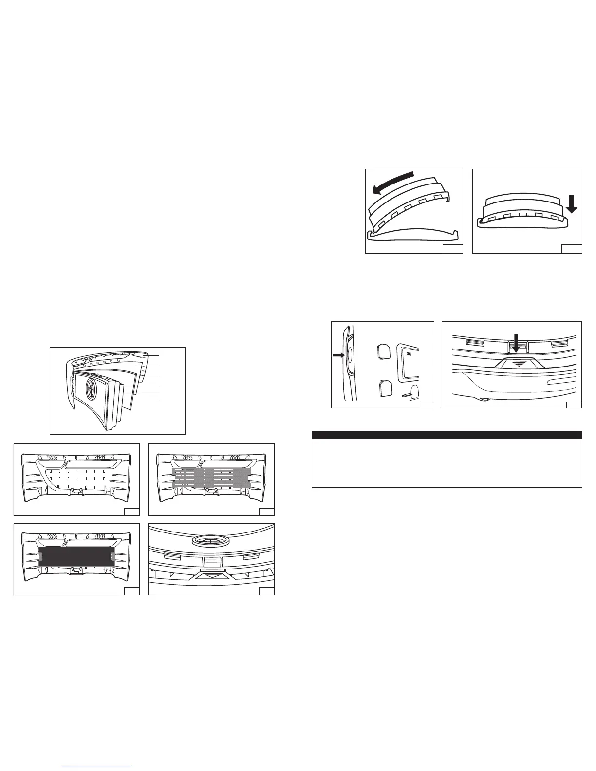
1. Inspect the lter/cartridge to be installed:
• Filter/cartridge is intact with no tears, cracks, distortion or other damage.
• The inner circular gasket is present and intact with no tears, cuts or distortions. Wipe the lter seal with a clean cloth
if necessary. Dispose of and replace lter/cartridge if damage is noted or suspected. NOTE: the 3M™ Versao™
Powered Air Purifying Respirator TR-600 Filter/Cartridge Assemblies have both an inner circular gasket (Fig. 4-6) and
outer rectangular barrier (Fig. 4-5). The inner gasket is the primary seal between the lter and blower. The outer barrier
acts to keep dirt and debris from behind the lter.
2. To install the lter/cartridge:
• Conrm the TR-600 is powered off. Do not install or replace lter/cartridges while the motor/blower is running.
Option 1: Using the lter/cartridge with prelter/spark arrestor and lter cover.
Fig. 5 (Recommended for most applications).
NOTE: Use the specied lter cover for the lter/cartridge. See Specications section for correct pairing.
• Hold the lter cover so it faces down (Fig. 5-1).
• (If required) Insert the metal mesh spark arrestor/prelter into the cover, ensuring the cutouts are aligned properly (Fig. 5-2).
• (If required) Insert the foam prelter, ensuring the cutouts are aligned properly (Fig. 5-3).
• Insert the lter/cartridge into the lter cover ensuring the bottom latching tab snaps into place (Fig. 5-4). The
lter/cartridge label must be visible in the cover window (Fig. 15).
• Place the hinge side of the lter/cartridge into the motor/blower (Fig. 6-1) and snap latch side into the lter latch (Fig. 6-2).
• Gently tug on lter/cartridge to ensure proper attachment at both sides.
Option 2: Using the lter/cartridge without the lter cover.
(May typically be used in applications when lter/cartridges are changed very frequently to reduce potential for cross-contamination.)
NOTE: Using the lter/cartridge without the lter cover leaves it more susceptible to damage from external forces and liquid spray.
•
Place the hinge side of the lter/cartridge into the motor/blower hinge (Fig. 6-1) and snap latch side into the lter latch (Fig. 6-2)
.
• Gently tug on lter/cartridge to ensure proper attachment at both sides.
1
2
6
3
5
4
1. Filter cover
2. Spark arrestor/prelter
3. Prelter
4. Filter/cartridge
5. Outer barrier
6. Inner gasket
Fig. 4
5-1
5-3 5-4
5-2
Fig. 5 – Installing lter cover, spark arrestor, and prelter
6-2
6-1
Fig. 6 – Latching the lter/cartridge
3. Removal of the lter/cartridge and cover:
• Turn the unit off. Do not remove the lter/cartridge with the motor/blower running.
• Hold the unit so the back (belt side) faces you.
• Press the blue lter latch on the left side. Pull the lter/cartridge out and away from the motor/blower (Fig. 7-1).
• Remove the lter/cartridge cover. Hold the lter/cartridge upside down. Pull out on the blue tab at the bottom of the
lter cover to unlatch it from the lter/cartridge. Pull the cover down and away from the lter/cartridge (Fig. 7-2).
NOTE: Pointing the unit down while removing the lter/cartridge helps prevent any built up material from falling into the
motor/blower area underneath the lter/cartridge.
7-1 7-2
Fig. 7
BATTERY PACK CHARGING & INSTALLATION
W WARNING
Always correctly use and maintain the lithium-ion battery packs. Failure to do so may cause re or explosion or could
adversely affect respirator performance and result in injury, sickness, or death.
a. Do not charge batteries with unapproved chargers, in enclosed cabinets without ventilation, in hazardous locations, or
near sources of high heat.
b. Do not immerse without the battery storage and cleaning cover installed.
c. Do not use, charge, or store batteries outside the recommended temperature limits.
d. Charge in an area free of combustible material and readily monitored.
There are two battery options for the 3M™ Versao™ Powered Air Purifying Respirator TR-600: the 3M™ Standard
Capacity Battery TR-630, and the 3M™ High Capacity Battery TR-632. Battery packs should be charged immediately and
fully upon receipt and after each use. Refer to TR-600 Chargers and Battery Packs User Instructions for additional information
on proper battery pack use, charging and maintenance. The run times for the TR-600 will vary for each conguration and is
dependent on headgear, lter/cartridge, selected airow, lter loading, battery selected, battery condition, and environmental
conditions. Refer to the TR-600 System Run Times Guide for additional information.
The battery packs do not require a learn cycle to calibrate or re-calibrate the battery pack charge indicator. However, it may
take up to three complete charge/discharge cycles for the battery to reach its maximum capacity and claimed run times.
Charge the battery pack
1. Inspect battery pack. If cracks or damage are noted, do not charge the battery pack. Properly dispose of the battery pack
and replace.
2. Place chargers in a cool, well-ventilated location free of particulates or other airborne contamination, that is readily
monitored.
3. Ensure the gold electrical contacts on the battery and charger are clean and free of debris. Insert the battery pack into the
3M™ Charger Cradle TR-640 by sliding the hinge end of the battery pack in rst. Push down to click the front end into
place (Fig. 8). Charging will begin.
 Loading...