Installing a Serial ATA RAID Controller
www.3ware.com 13
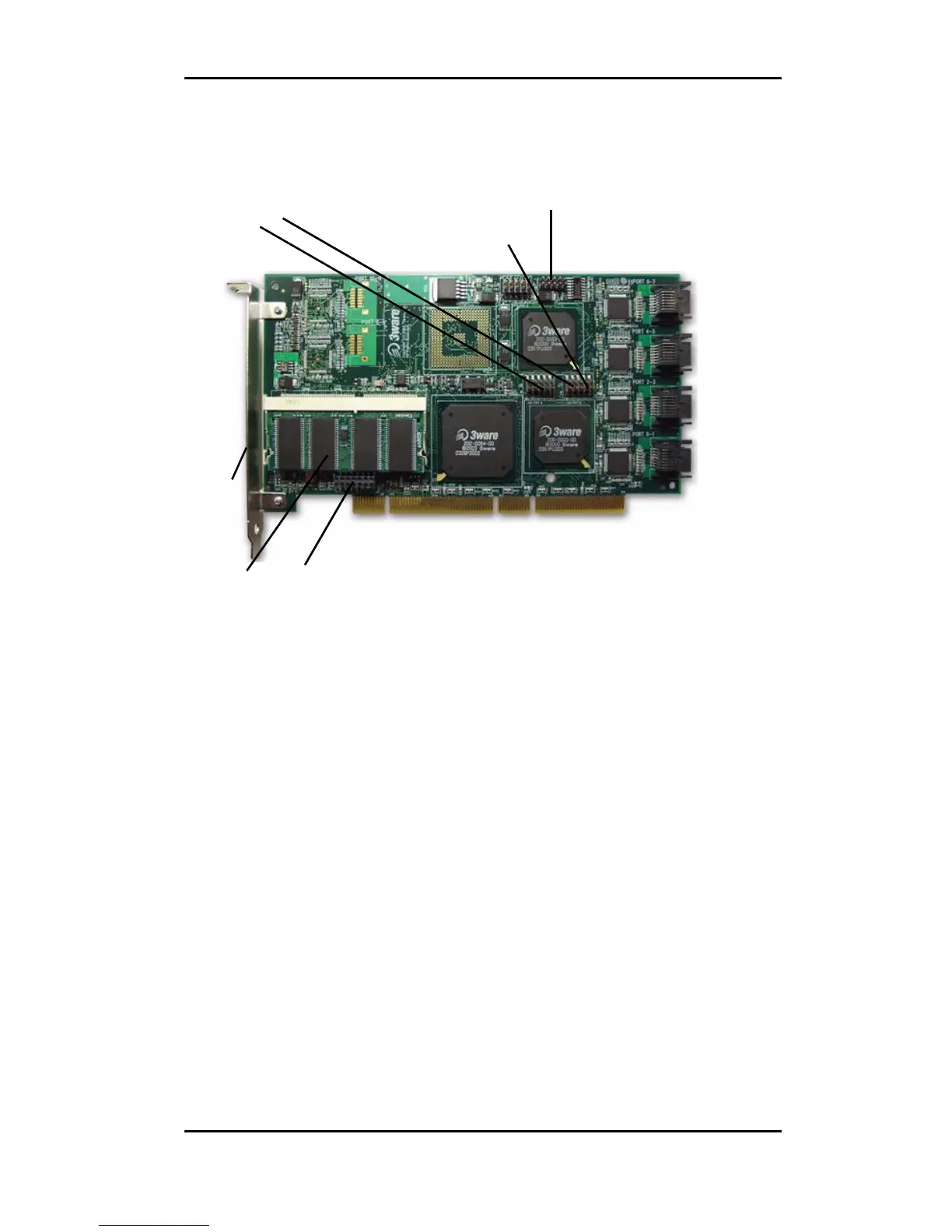
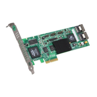
Figure 2. 8-Port 3ware 9500S-8 Serial ATA RAID Controller, Pchip
v1.5 (BBU-compatible)
Additional Details About the LED Status Connectors
As shown in Figures 1 through 5, LED connectors for individual
drives are on J7, J8, and J9 for the full size cards, and on J3 for the
half-size 4-port card.
Pin 1 is located in the lower left-hand corner of each 10-pin
connector. The odd-numbered pins, located on the bottom row, are
3.3V for the anode side of each LED to be connected. The even-
numbered pins are the return or cathode side.
Table 1 summarizes the LED indicator pin positions for the
different controllers.
LED indicators
for individual
drives on J7
and J8
Overall LED drive status
indicator: the last two pins
of J7. The anode is the
lower of the two pins and
the cathode is the upper.
Serial
number
(on plate)
Ports:
6 and 7
4 and 5
2 and 3
0 and 1
Serial ports are double-
stacked connectors.
Odd-numbered ports 1
through 7 are located
below even-numbered
ports 0 through 6.
SODIMM
(memory
module)
I
2
C
connector
LED connector details
J7 is for drives 0, 1, 2, 3 (left to right)
J8 is for drives 4, 5, 6, 7 (left to right)
The last two pins on
J7 and J8 are unused.
BBU (Battery
Backup Unit)
connector