4B - W4005 BÜHLER ELEVATOR MONITORING SYSTEM R9.6 – 22 May 2020
Page 12 of 48
8. Mechanical Installation
DANGER: EXPOSED BUCKETS AND MOVING PARTS WILL CAUSE SERIOUS INJURY OR
DEATH. THE OPERATOR MUST ALWAYS LOCKOUT POWER BEFORE REMOVING COVER OF
THE INSPECTION DOOR OF THE ELEVATOR OR PERFORMING ANY INSTALLATION OR
MAINTENANCE WORK.
8.1 TS1V4AI /B – TouchSwitch™ Alignment Sensor
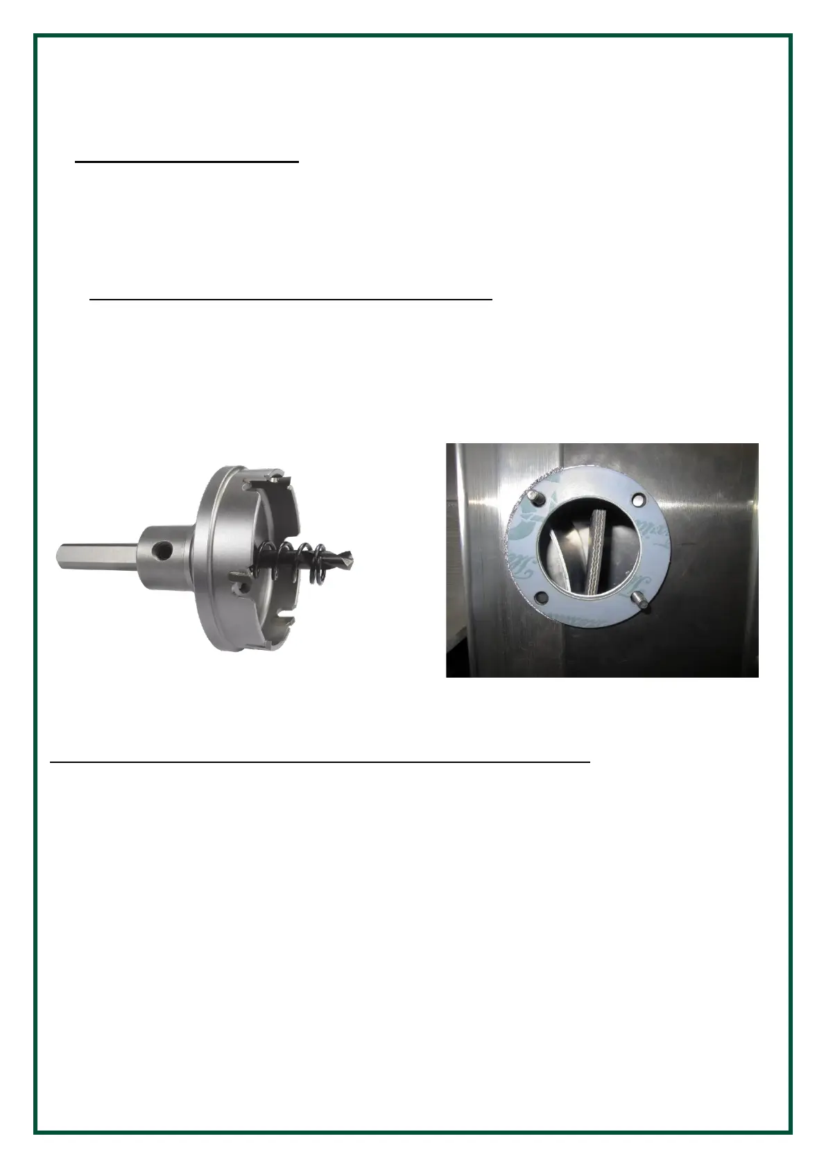
The TouchSwitch™ hole should be cut into the housing with a 55mm diameter hole saw (Figure 2), centered
on the edge of the belt. The hole should be cleaned and de-burred to avoid the TouchSwitch™ puck binding
and giving false misalignment alarms. You can mount the TouchSwitch™ with 2 of the 4 flange holes,
provided they are diagonal from one another (Figure 1). The enclosed flange shims can be used as a template
to properly place the flange holes. The TouchSwitch™ needs to be mounted on a flat surface, preferably with
the cable entrance between the 3 to 9 o’clock.
Figure 2 – TouchSwitch Mounting Hole Drill
The TouchSwitch™ can be mounted using one of the following three methods:
a) Drill and tap the machine casing for M6 threaded bolts supplied with the system. Make sure that the
bolts used to secure the TouchSwitch™ are short enough that they do not interfere with the operation
of the machine
b) Use threaded rivet nuts for M6 threads. The length of the rivet nut will depend on the thickness of
the machine’s casing. Make sure that the bolts used to secure the TouchSwitch™ are short enough
that they do not interfere with the operation of the machine
c) CD weld M6 x 30mm threaded welding studs to the machine casing
When placing flange shims on TouchSwitch™ make certain belt and or pulley contacts the TouchSwitch™
face before it can contact any internal surface of leg or conveyor housing. It is best not to be any further
away from the pulley than 30mm to 40mm to the face of the TouchSwitch™.
 Loading...