20
uniformly linked. As water ow is decreased the temperature
rise will increase and as water flow is increased the
temperature rise will decrease. Because of this relationship
between temperature rise and ow rate this test can be
useful to determine if the flow rate through the heat
exchanger is adequate. Other factors may also a ect water
ow rate and temperature rise such as debris or lime scale
build up inside heat exchanger or water pump operation.
If the temperature rise through the HPWH is consistently
lower than 8°F the outlet (supply) valve can be throttled
slightly closed to reduce the water ow rate. This may be
necessary on installations with a minimum of water piping
between the HPWH and the water system or tank.
Throttling should be done in small increments, no more
than 1/8 turn of the valve handle at a time. The HPWH
must be allowed to run for approximately 5 minutes
between each adjustment before the temperature rise
is measured again. If the outlet valve is throttled during
start up, mark the valve position and remove the valve
handle to ensure it is not accidentally changed.
If the temperature rise through the HPWH is consistently
greater than 12°F the water ow may be restricted. Ensure
all water valves between the HPWH and the tank or water
system are fully open. Ensure the e x t e r n a l water pump
is running. If the temperature rise continues to be excessive
call the toll free technical support phone number: 1-833-
447-3201.
5. Using thermometers or temperature sensors, measure
the temperature of the incoming source water to the
HPWH and the outgoing source water leaving the unit.
The outgoing temperature should be 12°F to 20°F (7°C to
13°C) cooler than the incoming. The higher the ow rate
the lower the temperature di erential will be
6. When all of the above procedures are complete adjust
the tank temperature control set point to desired system
temperature, not to exceed 150°F (66°C). Remove all test
instruments and replace all cabinet doors.
GOAL: Achieve a 3-4 GPM ow rate through the condenser by
using the lower limit input.
WHY: Every piping system is di erent therefore they have
di erent head losses in the system. In order for the AO Smith
heat pump to operate e ciently and meet the supply demands
e ectively it is important to set the lower limit of the control
valve to meet the minimum water ow rate requirements for
the heat pump. The optimal ow rate is 3-4 GPM which allows
the unit to sense that there is ow, while also maintaining a
high change in temperature between the entering and leaving
water. It is strongly advised to write down the control valve
lower limit for this system in the case that the system must be
purged again.
HOW:
1. Access the con guration screen on the heat pump hot
water heater
2. Input a lower limit value between 20 and 100
3. Press purge & wait 30 seconds for ow in the system to
become consistent
4. Observe if the goal of 3-4GPM has been met (this value
will uctuate slightly on the screen)
A. If the GPM is too high reduce the lower limit value
B. If the GPM is too low increase the lower limit value
5. Repeat this process until the goal of 3-4GPM has been
achieved.
Lower Limit Value: ___________________
PUGING THE CONDENSE ON A PLC
WATE HEATE
Access the con guration screen on the heat pump hot water
heater. Set the “lower limit” value to 100 to open the control
valve all the way, then press the purge button to run the pump.
(The pump will remain running for 2 minutes unless the button
is pressed again to stop the purge cycle) While the pump is
running bleed any air out of the water lines. The “CondFlow”
value will re ect the ow rate through the condenser of the
unit, the default value is 2 so when it is constantly above 2 the
unit is owing properly.
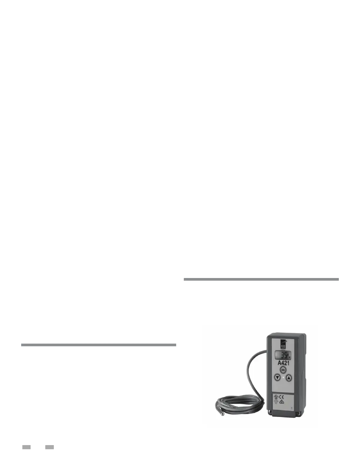
The unit comes standard with a Johnson Controls A421 Model
# A421GBF-x controller. This control is used to control the water
temperature in the tank by supplying a call signal to the Heat
Pump Water Heater. The control comes with some factory
settings.
The A421 control should never be set higher than
160°F, failure to comply could void the warranty.
Johnson Controls A421 Controller
Model # A421GBF-x
SETTING LOWER LIMIT CONTROL
VALVE LIMIT FOR SINGLE-PASS
ELECTRONIC TEMPERATURE
CONTROLS
 Loading...