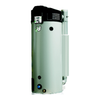
Instruction manual BFC 43
is
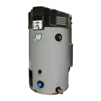
BFC 80 t/m 120 - CO
2
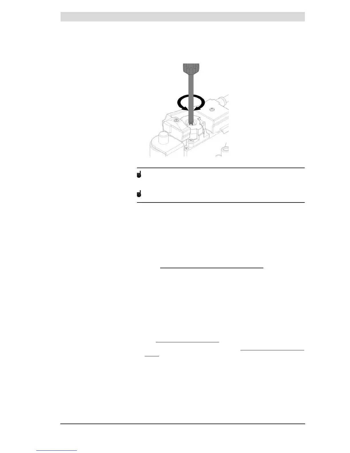
adjustment (partial load)
Note
Turning to the left (anticlockwise) means more less (lower CO
2
level) and
turning to the right (clockwise) means more gas (higher CO
2
level).
Note
After conversion, you must check that the gas control valve is gastight.
23. Remove the CO
2
measurement probe from the measurement nipple of the
flue gas outlet pipe.
24. Put the cap back on the measurement nipple of the flue gas outlet pipe.
25. Shut off the gas supply.
26. Replace the covers.
3.11.4 Switching pressure measurement
To measure the switching pressure, proceed as follows:
1. Isolate (10.3 "
Isolating the water heater from the mains") the appliance from
the power supply.
2. Carefully remove the covers from the appliance.
3. The electrical section is now visible.
4. Remove the black caps from the measurement point of the pressure switch.
5. Connect the + of the pressure gauge to the H of the measurement point of
the pressure switch.
6. Connect the - of the pressure gauge to the L of the measurement point of
the pressure switch.
7. Zero the pressure gauge.
8. Start (9 "
Starting the water heater") the appliance.
9. The appliance will now run the heating cycle (9.3 "
The appliance's heating
cycle").