11
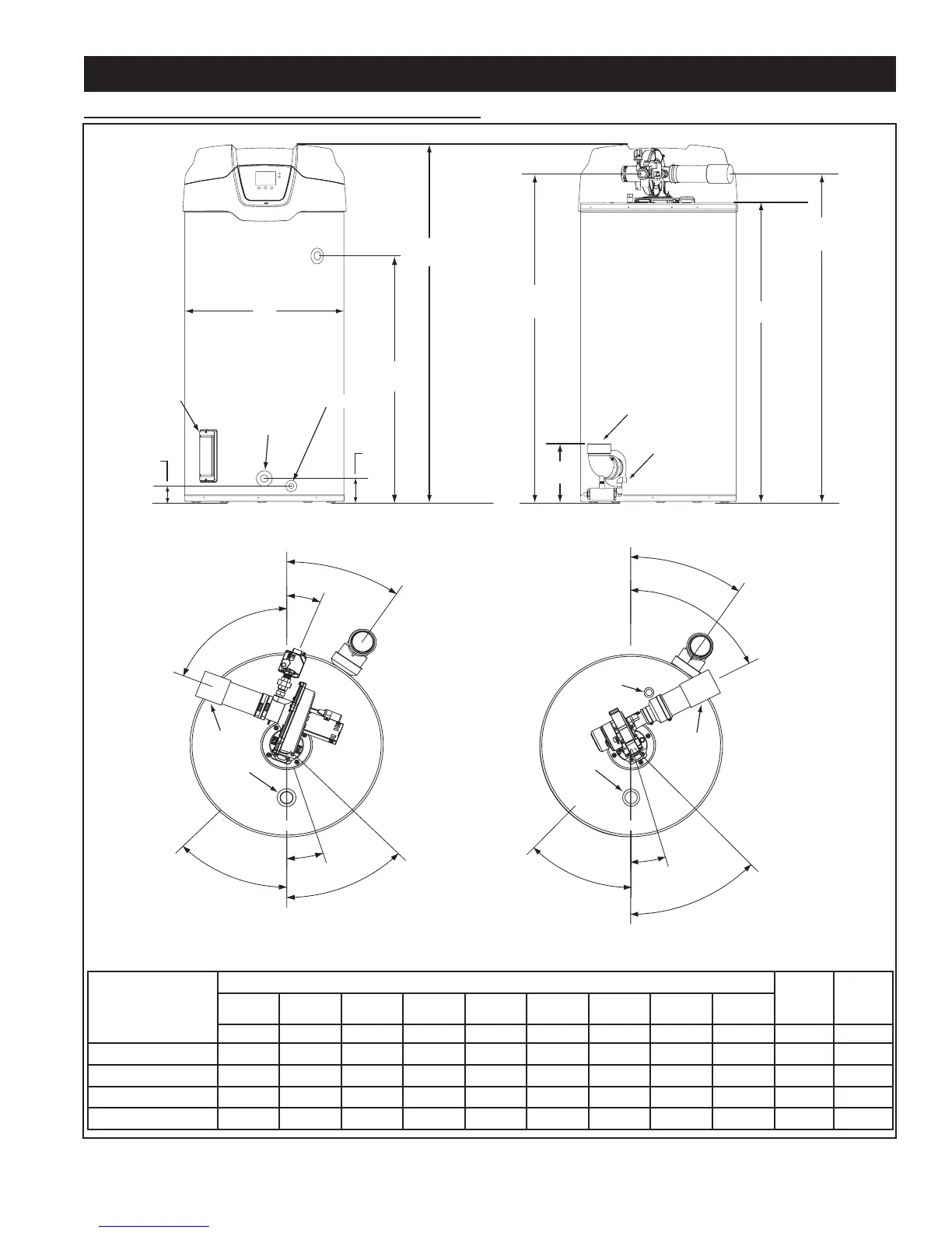
ROUGH IN DIMENSIONS
INSTALLATION CONSIDERATIONS
FRONT BACK
CLEANOUT
T & P VALVE
3/4” NPT DRAIN
1 1/2” NPT
WATER INLET
VENT CONNECTION
3 INCH PVC
(exhaust elbow)
CONDENSATE
DRAIN CONNECTION
1/2 INCH PVC
INTAKE AIR CONNECTION
3 INCH PVC
SUPPLY GAS
CONNECTION
E
H
D
C
A
I
G
F
B
WATER OUTLET
HEIGHT
These designs comply with the current edition of the American National Standard for Gas Water Heaters, Volume III, ANSI Z21.10.3 / CSA 4.3
as an automatic circulating tank water heater, and automatic storage water heaters.
120,000 & 150,000
Btu/hr
MODELS
199,000 & 250,000
Btu/hr
MODELS
* Center line of water outlet on top of the water heaters is approximately 7 inches from the front edge of the water heater.
TOP VIEWS
45°
18°
CL
E
ANO
U
T
T &
P
V
AL
V
E
D
RA
I
N
V
A
L
V
E
45°
35°
64°
*1 1/2” NPT
WATER
OUTLET
SUPPLY GAS
CONNECTION
VERTICAL
FRONT
INTAKE AIR
3 INCH PVC
VENT
3 INCH
PVC
35°
22°
68°
45°
18°
45°
CLE
AN
O
UT
T
&
P
V
A
L
V
E
D
R
A
I
N
V
A
L
V
E
*1 1/2” NPT
WATER
OUTLET
FRONT
INTAKE AIR
3 INCH PVC
GAS
VENT
3 INCH
PVC
MODEL
DIMENSIONS
SHIP
WEIGHT
STD
SHIP
WEIGHT
ASME
A B D E G H I
BTH 120
BTH 150
BTH 199
BTH 250
Figure 6