Electrical
Verify the unit nameplate agrees with the
power supply. Connect power and control
field wiring as shown on the unit wiring
diagram provided with the unit.
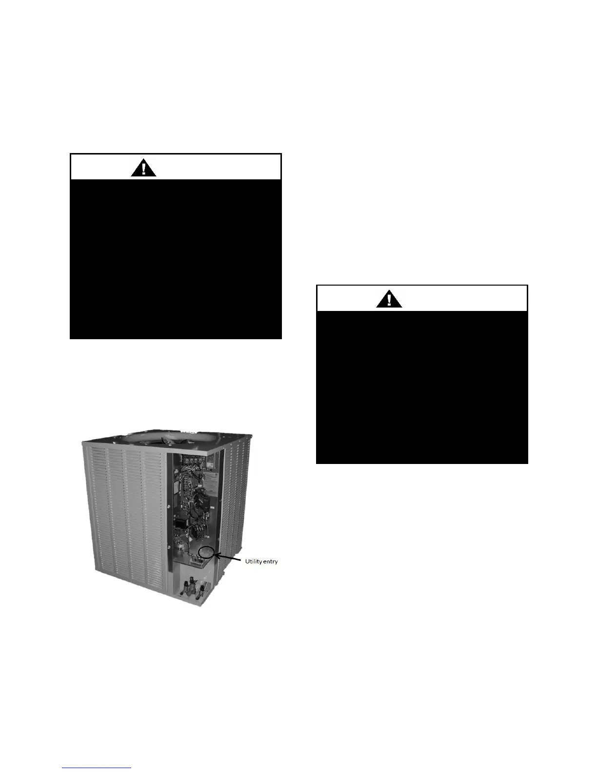
Route power and control wiring, separately,
through the utility entry right above the
service valves. Do not run power and signal
wires in the same conduit.
Figure 3 – Utility Entry
Size supply conductors based on the unit
MCA rating. Supply conductors must be
rated a minimum of 75°C.
Protect the branch circuit in accordance with
code requirements. The unit must be
electrically grounded in accordance with
local codes, or in the absence of local codes,
the current National Electric Code,
ANSI/NFPA 70 or the current Canadian
Electrical Code CSA C22.1.
Note: Units are factory wired for 208V,
230V, 460V or 575V. In some units, the
208V and 230V options may also be
provided in single or three phase
configurations. The transformer
configuration must be checked by a
qualified technician prior to startup.
Wire power leads to the unit terminal block.
All wiring beyond this point has been done
by the manufacturer and cannot be modified
without affecting the unit's agency/safety
certification.
All units require field supplied electrical
overcurrent and short circuit protection.
Device must not be sized larger than the
Maximum Overcurrent Protection (MOP)
shown on the unit nameplate.
Codes may require a disconnect switch be
within sight of the unit.
3-PHASE ROTATION
Rotation must be checked on all
MOTORS AND COMPRESSORS of
three phase units. Condenser fan
motors should be checked by a
qualified service technician at startup
and any wiring alteration should only
be made at the unit power
connection.
ELECTRIC SHOCK
Electric shock hazard. Before
attempting to perform any installation,
service, or maintenance, shut off all
electrical power to the unit at the
disconnect switches. Unit may have
multiple power supplies. Failure to
disconnect power could result in
dangerous operation, serious injury,
death or property damage.