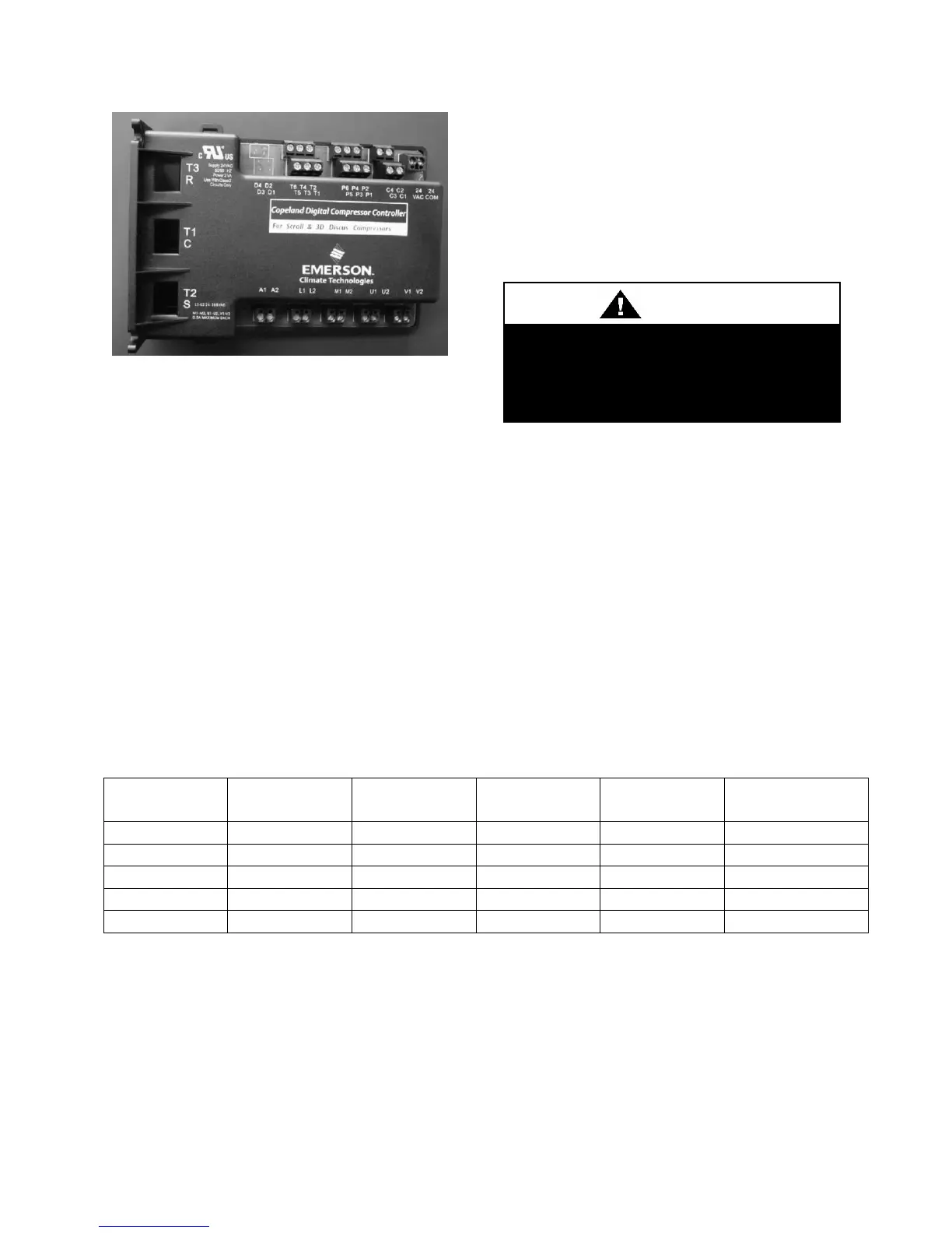
Figure 7 - Variable Capacity Compressor
Controller
Low Voltage Terminals
24COM Module Common
24VAC Module Power
C1 & C2 Demand Input
P1 Pressure Common
P2 Pressure Input
P3 Pressure Power 5VDC
P4 Pressure Shield
P5 & P6 Pressure Output
T1 & T2 Discharge Temperature Sensor
High Voltage Terminals
A1 & A2 Alarm Relay Out
M1 & M2 Contactor
L1 Control Voltage N
L2 Control Voltage L
U1 & U2 Digital Unloader Solenoid
V1 & V2 Vapor Injection Solenoid
The compressor controller modulates the
compressor unloader solenoid in an on/off
pattern according the capacity demand
signal of the system. The following table
shows the linear relationship between the
demand signal and compressor capacity
modulation. The compressor controller also
protects the compressor against high
discharge temperature. Refer to Table 7 for
the relationship between thermistor
temperature readings and resistance values.
Table 6 - Demand Signal vs. Compressor Capacity Modulation
To avoid damaging the compressor
controller, DO NOT connect wires to
terminals C3, C4, T3, T4, T5, or T6.