System Overview
12 Document Number: D1000092204 B
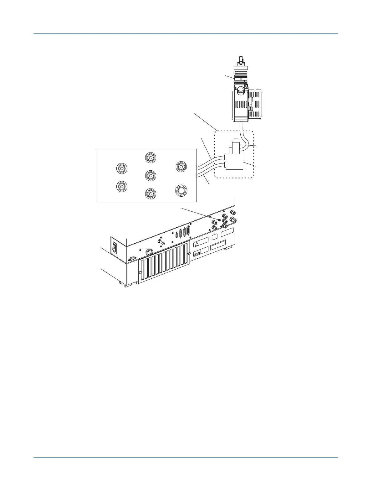
Figure 1-9 Source exhaust system
A filtered nitrogen or zero air gas supply (oil free) is delivered to the source
exhaust pump at pressures indicated on the gas panel at the back of the
instrument. The preceding figure shows the exhaust supply connection points for
the API 3200 instrument.
Vacuum Chamber
The vacuum chamber houses the mass filter rail, including the ion optics, the
quadrupole rod sets, the collision cell, and the ion detector.
Shutting Down and Turning on the System
Use the following procedures if you need to shut down or turn on the system.
To shut down the system
1. In the Analyst
®
software, complete or stop any ongoing scans.
2. Turn off the sample flow to the instrument.
E
XH
A
U
S
T
S
U
PP
L
Y
M
IN
55
P
S
IG M
AX
60
PS
IG
SHE
A
T
H
G
A
S
MA
X
105 P
SI
G
C
A
D
G
AS
M
AX
60
PSI
G
C
A
D
G
AS
V
ALVE
WASTE OUT
E
XH
A
U
S
T
WAS
T
E
O
U
T
CURTA
IN
G
AS
S
UP
P
LY
Ma
x
6
0
PSIG
GAS
1/G
A
S
2
Ma
x
1
0
5P
S
IG
S
E
R
I
A
L
S
O
U
R
C
ES
A
U
XI/
O
I
E
E
E
-
4
88
207
-
24
2V
50-60
H
z10
A
B
A
C
K
I
N
G
P
UMP
Gas Panel
Front Bulkhead
Assembly
Pressure
Switch
Venturi
Pump
Exhaust Waste Out
Exhaust Supply
Ion Source
EXHAUST SUPPLY
MIN 55 PSIG MAX 60 PSIG
SHEATH
GAS
MAX 105 PSIG
CAD
GAS
MAX 60 PSIG
VALVE
WASTE OUT
EXHAUST
WASTE OUT
CURTAIN GAS
SUPPLY
MAX 60 PSIG
GAS 1 / GAS 2
MAX 105 PSIG