4.2.0 INSTALLATION OF
THE SENSOR LINES
NOTE:
The sensor must be installed with the
utmost precision, as this is of decisive
importance for the sauna climate.
The sensor lines must not be installed
together with power cables and must not be
led through common holes, as this may cause
electronic malfunctions!
The sensor lines are not temperature-
resistant – therefore, they must be installed
outside the cabin or in the cabin wall!
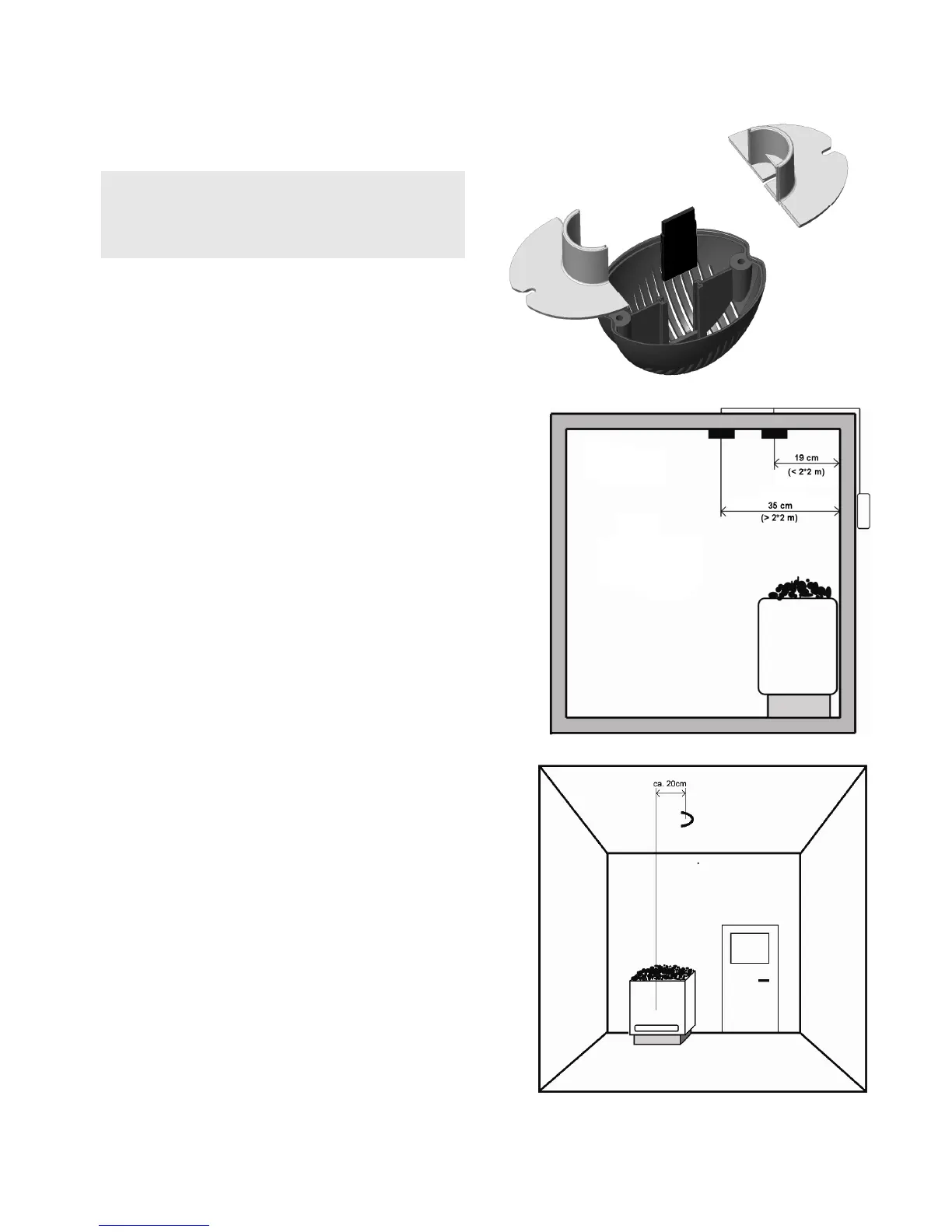
4.3.0 INSTALLATION OF THE
HEATER SENSOR
The (4-pole) heater sensor is comprised of a
temperature sensor and a thermal safety
release. The sensor housing is mounted on
the cabin ceiling above the sauna heater.
For the respective dimensions please refer to
illustrations 5 and 6. Please note that the
installation distance to the cabin wall must
be 19 cm for sauna cabins up to 2 x 2 m and
35 cm for bigger cabins, unless some other
position is explicitly noted in the cabin
description.
A 31 mm diameter hole is drilled (by means of
a cavity wall drilling machine) through the
cabin ceiling at the designated spot in the
centre of the profiled board.
The temperature sensor and the thermal
safety release are connected with the lines by
means of plugs.