36 OI/266CXX/266JXX/HART-EN Rev. B | 266CRx, 266JRx, 266CSx, 266JSx
Replace mode (DIP switches 1 and 2)
In normal mode the DIP switches 1 and 2 are in position 0. If a
replacement procedure is necessary, they will be activated.
When replacing the electronics or the sensor, disconnect the
power supply and move DIP switch 1 to position 1.
When replacing the secondary electronics, disconnect the
power supply and move DIP switch 2 to position 0.
The sensor can be replaced when DIP switch 2 is in
position 1.
IMPORTANT (NOTICE)
We recommend resetting the corresponding DIP
switch to position 0 after each replace operation.
Push buttons
mode (DIP switch 3)
DIP switch 3 is factory-set to position 1. This means that the
the zero pushbutton (Z) sets the PV offset (bias) value (bias =
current digital measured value) to 0 and the span push button
resets the PV offset (bias) value set to 0 with (Z).
If this DIP switch is on position 0, the zero button (Z) and the
span button (S) are used for setting the start of the measuring
range (zero) and measuring voltage (span). For this the
appropriate pressure for the values to be set must be
specified.
IMPORTANT (NOTICE)
F
or 266Cxx transmitters, we recommend leaving
DIP switch 3 in position 1 at all times.
Fail mode (DIP switches 4 and 5)
Users wishing to modify the factory-set parameters for the
alarm current (in the event of a transmitter failure) must set DIP
switch 4 to position 1.
Consequently, users must select whether the output is to
change to the minimum or maximum output current.
DIP switch 5:
— The output is high in position 0
(> 20 mA to 22 mA; please specify exactly)
— The output is low in position 1
(< 4 mA to 3.7 mA; please specify exactly)
11.3 Factory s
ettings
The transmitters calibrated in the factory to the measuring
range specified by the customer. The calibrated measuring
range and the measuring point tag are specified on an
additional labeling plate. If nothing is specified by the
customer in this regard, the transmitter will be delivered with a
standard configuration, that contains the following parameters
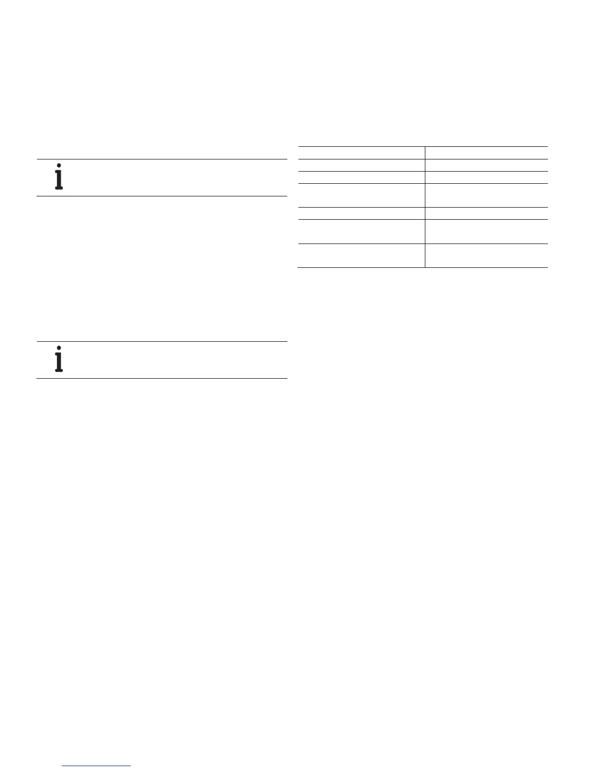
(among others).
Parameter Factory setting
Measuring range start (LRV) (4 mA) Zero
Measuring range end (URV) (20 mA) Upper measuring range limit (URL)
Transmission function for the output Mass flow for 266Cxx
Linear for 266Jxx
Damping 1 second
Safety mode at transmitter failure
(alarm)
High alarm (21.8 mA)
Presentation of the optional LCD
display
Process value PV (1-place) and
bar diagram of the output signal
Each of the parameters listed here can be easily set via the
optional LCD display with operating menu, a HART handheld
terminal or a compatible software solution.

 Loading...


