266CRx, 266JRx, 266CSx, 266JSx | OI/266CXX/266JXX/HART-EN Rev. B 55
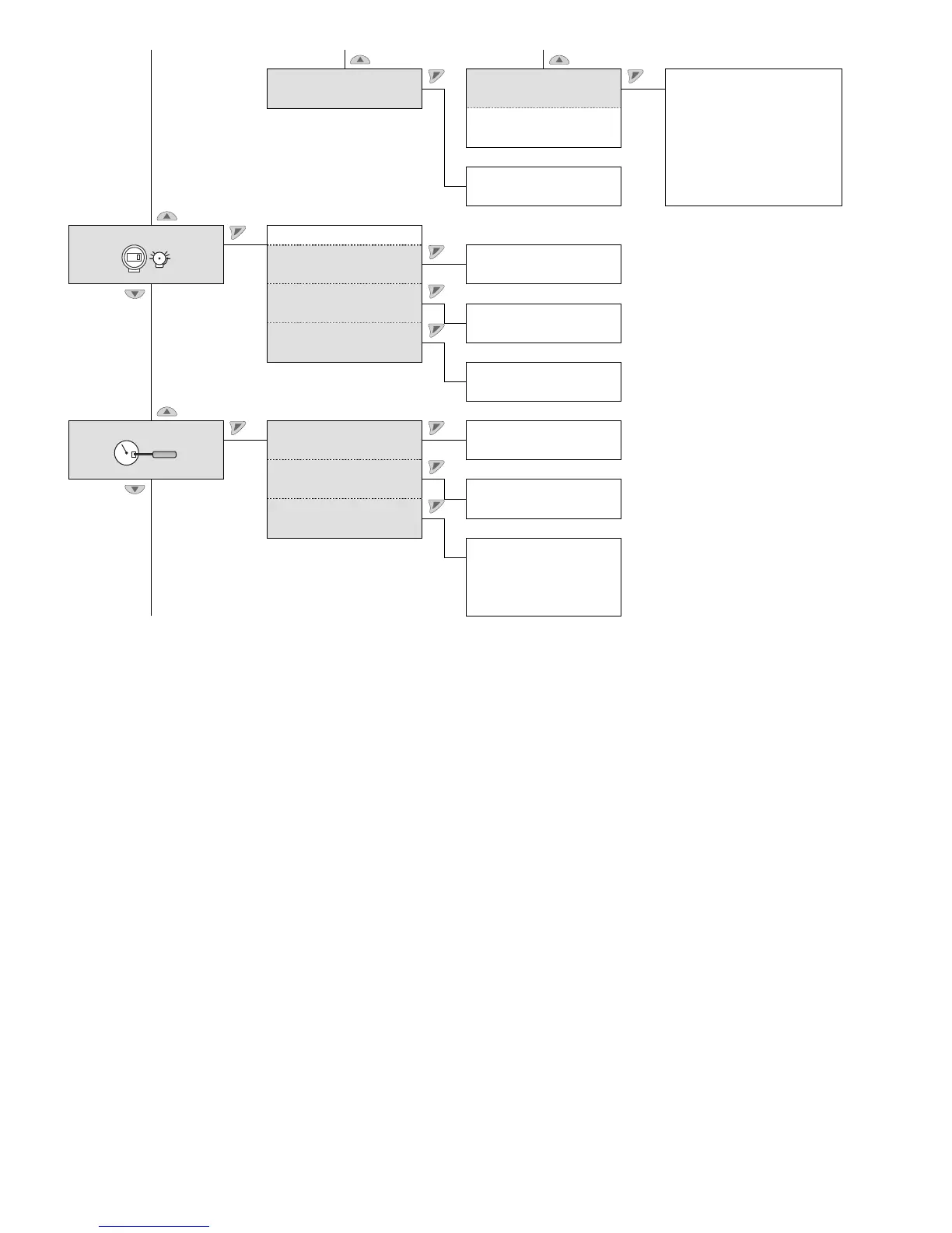
Security Display Unit Pressure
Flow
Mass & Volume
Density
Level
Other
Custom Unit
Lower Range Value
Upper Range Value
Display Protection
Change Password
Process Alarm Fail Safe Type
Fail Safe Level Down
Up
Saturation Limits
Low Saturation
High Saturation
Process Alarm
Low Alarm
High Alarm
Calibration Main Pressure Sensor Low Trimming
High Trimming
Output
Set 4 mA
Set 20 mA
Reset
Factory Sensor Trimming
User Sensor Trimming
Factory Output Trimming
Noti
ce regarding menu “Process Alarm”
In this menu the behavior of the analog output current (current limits) for measuring range overshoots and alarm states can be
configured. As long as the process value moves within the already set span, the output signal is between 4 and 20 mA. If the
process value (PV) underranges the lower range value (LRV), the signal will be set to the configurable lower current limit; if the
process value exceeds the measuring range end URV), the signal will likewise be set to the configurable upper current limit.
If the diagnostic function of the transmitter detects an error, the signal will be set to high alarm or low alarm, depending on the
user-defined setting.
The parameter “Fail Safe Level” (Fail Mode) can be adjusted via the DIP switches 4 and 5 of the electronics module. The precise
value that the signal assumes can be set via the “Process Alarm” menu. In this process the limit for the low alarm current must
be below the lower current limit and the limit for the high alarm current must be above the upper current limit.

 Loading...


