Smile_Tina_Manual_(English)_v1A
www.jokabsafety.com
2010-10-19
8
5 Operation
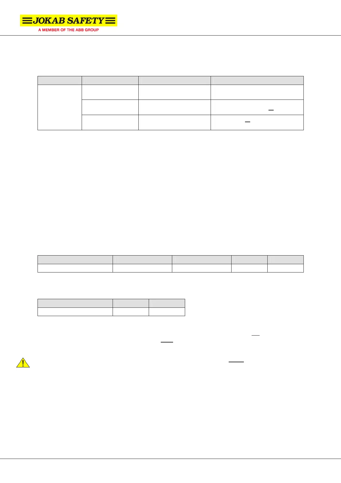
LED indication
LED Indication Description Input signal on pin-2
Green
Safety circuit closed
(protection OK)
Dynamic signal in
Green-Red (flash)
Safety circuit open
(protection OK)
No dynamic signal in or 0 VDC in
LED on Tina
Red
Safety circuit interrupted
(protection open)
+24 VDC in or
safety circuit
interrupted
Information output signal attributes
The information output of the unit (pin-5) is set either high (+24 VDC) or low (0 VDC) depending on
four different input signals (pin-2):
• Dynamic signal - Dynamic signal input exist, i.e. the safety circuit is OK up until this unit
• No dynamic signal - Dynamic signal input does not exist, i.e. the safety circuit is interrupted
before this unit.
• +24 VDC - A constant +24 VDC signal is applied = high (H)
• 0 VDC - The pin is connected to 0 VDC = low (L)
The information output signal depends on the input signal according to the table below. Note that if the
safety is interrupted; i.e. if the emergency button is pressed, the information output signal is always
low (L).
Input signal (pin-2) Dynamic signal No dynamic signal +24 VDC 0 VDC
Info output signal (pin-5)
High High Low High
The delay for switching the information signal output from high to low (H Æ L) and low to high (L Æ H)
is given in the table below.
Info output signal switch H Æ L L Æ H
Delay ~ 12 ms ~ 0 ms
NB: If the unit detects an error (short circuit or interruption) lasting shorter than 13 ms the information
output signal is set to low for 1.2 s (1200 ms) and then set to high again. This does not
affect Vital
since it needs 22 ms to release. Pluto however does
release, which means that a filter (20 ms) must
be implemented if this function is needed.
Warning! The information output signal is not a failsafe signal and should never
be used for the
safety purpose(s).
 Loading...


