Chapter 2 - Start-Up Instructions
DCS 500B / DCP 500B Operating Instructions IV A 2 - 17
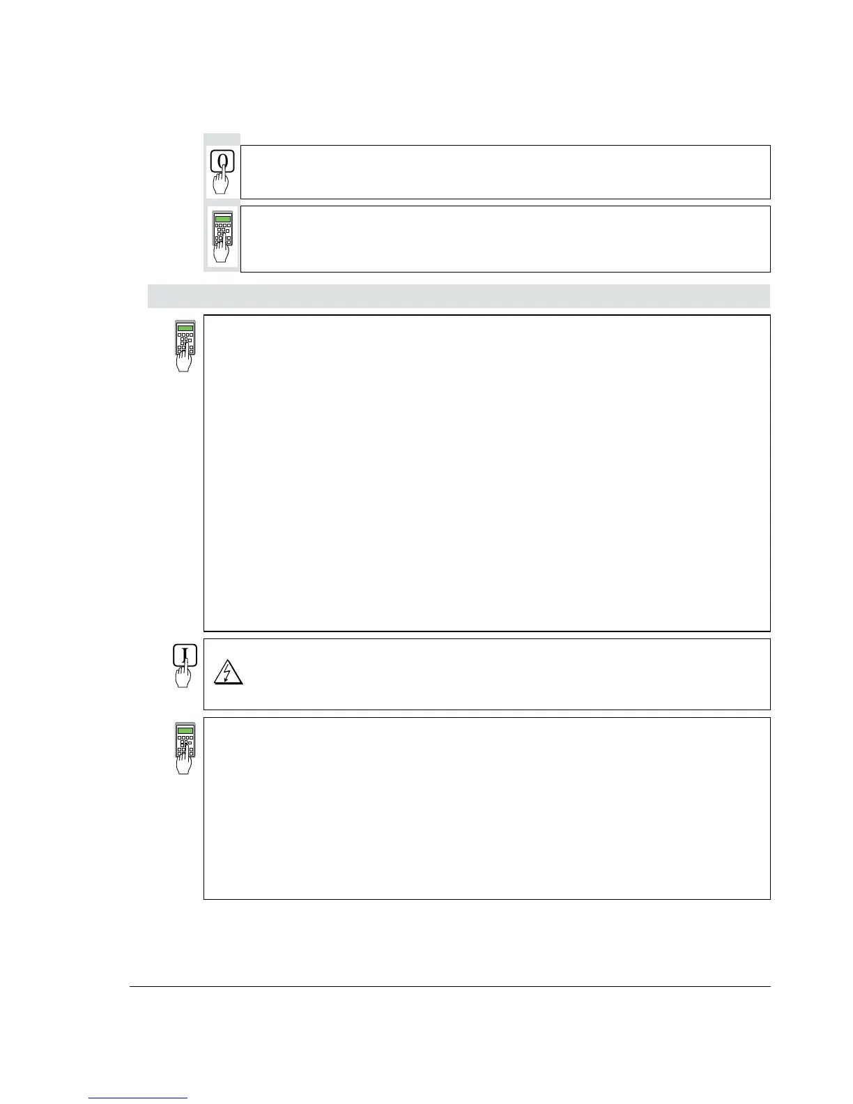
Switch OFF power!
1201 = 0 Panel display: NOT ACTIVATED
11202 = SAVE MOT1 SET
Save the altered values in the non-volatile memory!
When unit is fitted either with an SDCS-CON-1 or SDCS-CON-2 control board!
1001 = 1 Panel display: EMF, NO FIELD REV
Field weakening activated.
1002 = 12522
Links up a settable parameter as the flux reference value.
1004 = 12502
Activates the linked-up parameter.
1009 = 0
1010 = 0
e.m.f. controller switched off.
1012 = Speed at field weakening point as per motor rating plate
1013 = 40,0
1014 = 70,0
1015 = 90,0
Linear characteristic of field
12522 = 4095
Flux reference value set to 100 % corresponding to 4095.
12516 = 2000
Set internal reference value to 10 %.
Switch ON power; start drive.
DANGER: System components now energized!
Drive should run at 10 %.
The next steps serve to determine the motor's field characteristic. For this purpose,
the internal reference is used to set a speed n which is within the motor's basic speed
range and can be easily converted into 90 %, 70 % and 40 %.
Example: if n is selected so as to produce a motor voltage of 300 V, then 90 % will
correspond to 270 V, 70 % to 210 V and 40 % to 120 V.
12516 = increase slowly until a motor voltage is produced which can be
easily converted.
Note: Measure motor voltage with the U ARM AC signal
(change between ACT and PAR).
Scaling of 12516: 20000 corresponds to 100 % speed.