Chapter 5 – Standard Application Macro Programs
ACH 500 Programming Manual 5-13
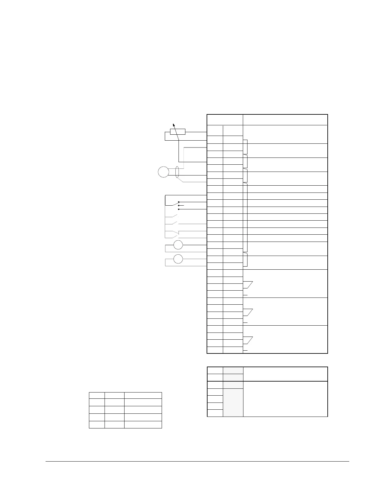
Pump and Fan External
Connections
Connection Example
Figure 5-8 Connection Example
1
2
3
4
5
6
7
8
9
10
11
12
13
14
15
16
17
18
19
20
21
22
23
24
25
26
27
28
29
REF
GND 2
AI 1+
AI 1-
AI 2+
AI 2-
SPL
GND 2
N.C.
SPL
DI 1
DI 2
DI 3
DI 4
DI 5
DI 6
AO 1+
AO 1-
AO 2+
AO 2-
RO 11
RO 12
RO 13
RO 21
RO 22
RO 23
RO 31
RO 32
RO 33
Function
Reference Voltage 10 VDC
Actual Signal (ACT1)
Reference Signal
Auxiliary Voltage Output 24 V DC
+24 V max. 10 mA
START HAND
AUTO SELECT**
RUN ENABLE
START AUTO
Output Frequency
Motor Current
Relay Output 1
FAULT
A
f
* Select voltage or current reference with plugs
S1 and S2 on the customer interface board (beside
the screw terminals 1-6 of X50.
** Open switch = Manual (direct speed setting)
Terminal X50
1
2
3
4
5
6
+8V Power to Remote Panel
RS485 Serial Link Connections
GND2
Shield1
GND3
SGNA
SGNB
7 Shield2
Transducer
Feedback
(B)
Manual
Speed Reference)
PT
10 mA
0 V - 10 V or 0 mA - 20 mA*
2 V - 10 V or 4 mA - 20 mA*
0V
Not Connected
0 - 20 mA <-> 0 - 50 Hz
0 - 20 mA <-> 0 - I
N
MOTOR 1
Relay Output 2
MOTOR 2
Relay Output 3
X51
Closed switch (+24V) = Automatic (PFC)
Preset Speed Select***
Preset Speed Select***
** Operation: D13 D14 Output
0
1
0
1
0
0
1
1
set freq. through AI1
Preset Speed 1
Preset Speed 2
Preset Speed 3
0 = Open
1 = Closed
Hand
Off
Auto