22 E-Bypass Configurations for ACH550 Drives
Installation
500…600 Settings
Switch Code
Default settings in (parentheses).
Output Contactor Control
In the unlikely event of failure in the bypass control electronics, the user can engage
the drive output contactor without the control electronics by moving jumper J2 to the
Output Contactor position – see "Adjustment Locations" on page 19. When the
jumper is in the Output Contactor position, the Drive contactor is energized and the
Bypass contactor is de-energized. The contactors, and therefore the system, are not
controlled by the bypass electronics when jumper J2 is in the Output Contactor
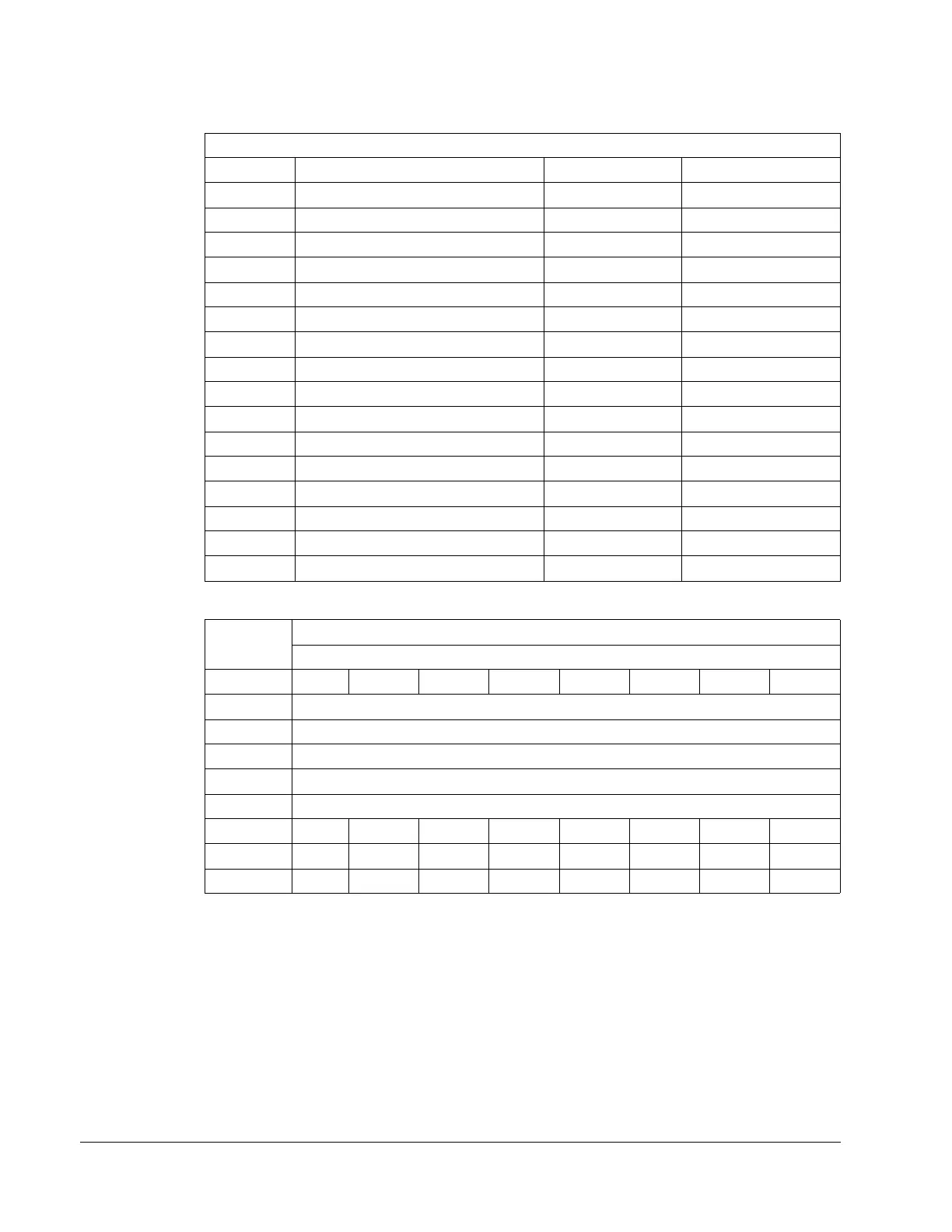
500…600 Volt, Codes for Overload Trip Current DIP Switch
HP Identification Frame Size Switch Code
2 ACH550-xx-02A7-6 R2 A
3 ACH550-xx-03A9-6 R2 A
5 ACH550-xx-06A1-6 R2 A
7.5 ACH550-xx-09A0-6 R2 A
10 ACH550-xx-011A-6 R2 A
15 ACH550-xx-017A-6 R2 B
20 ACH550-xx-022A-6 R3 B
25 ACH550-xx-027A-6 R3 C
30 ACH550-xx-032A-6 R4 C
40 ACH550-xx-041A-6 R4 D
50 ACH550-xx-052A-6 R4 D
60 ACH550-xx-062A-6 R4 D
75 ACH550-xx-077A-6 R6 E
100 ACH550-xx-099A-6 R6 E
125 ACH550-xx-125A-6 R6 F
150 ACH550-xx-144A-6 R6 F
Switch
Position
Switch Setting Configurations
Switch Code
A B C D E F G H
1 (OFF) / ON = Automatic Transfer Bypass Feature (OFF) / ON
2 (OFF) / ON = Mode / Override Relay RO4 (Mode) / Override
3 RESERVED (OFF)
4 OFF / (ON) = NEMA Class 30 / (NEMA Class 20) overload trip curve
5 RESERVED (OFF)
6 OFFOFFOFFOFFONONONON
7 OFF OFF ON ON OFF OFF ON ON
8 OFF ON OFF ON OFF ON OFF ON