30 ACH580 Installation, Operation and Maintenance Manual
ACH580-01 Installation
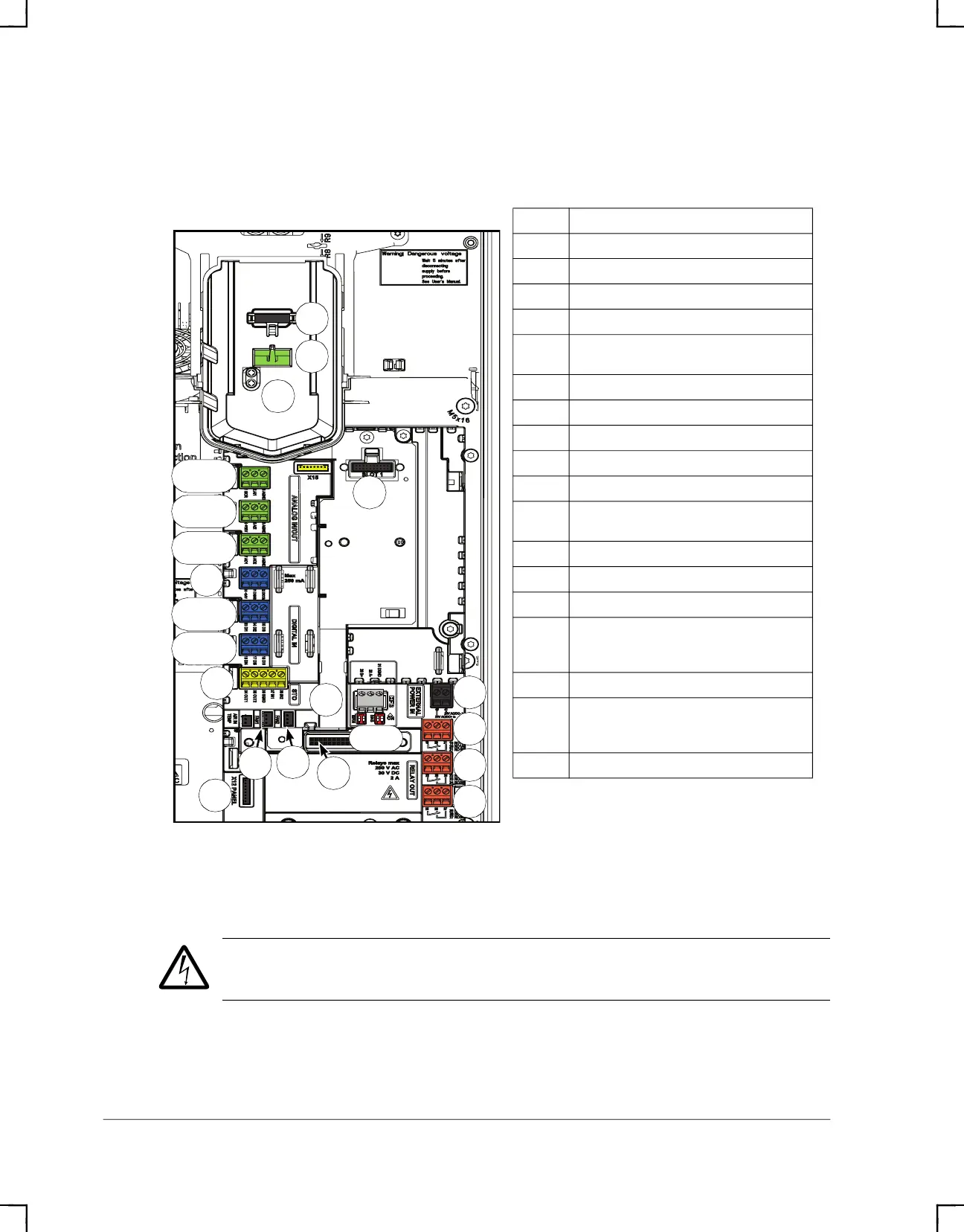
External control connection terminals, frames R6…R9
The layout of the external control connection terminals of frames R6…R9 is shown
below.
WARNING! If installing modules, the +24 V AC cable to the control board ground
when the control board is powered using an external 24 V AC supply.
2
X2
X4
X13
1
3
X8
X7
X6
X10
X5
S4, S5
X17
X16
X14
X12
R6…R9
X1:1…3
X1:4…6
X1:7…9
X3:1…3
X3:4…6
Description
X1 Analog inputs and outputs
X2 Aux. voltage output
X3 Digital inputs
X4 Safe torque off connection
X5
Connection to embedded EIA-485
fieldbus adapter module
X6 Relay output 3
X7 Relay output 2
X8 Relay output 1
X10 External +24 V AC/DC input connection
X12 Panel connection
X13
Option slot 1 (fieldbus adapter
modules)
X14 Option slot 2 (I/O extension modules)
X16 Auxiliary fan 1 connection
X17 Auxiliary fan 2 connection
S4, S5
Termination switch (S4), bias resistor
switch (S5), see section Switches on
page 43
1 Panel port (control panel connection)
2
Cold configuration connection. This
connector is used with the CCA-01
configuration adapter.
3 Power OK and Fault LEDs
ACH580_Inst_Op_Maint_Rev G.book Page 30