34 ACH580 Installation, Operation and Maintenance Manual
ACH580-01 Installation
WARNING! To avoid danger or damage to the drive on IT systems and corner
grounded TN systems, see section Drive compatibility for various electrical power
systems on page 16.
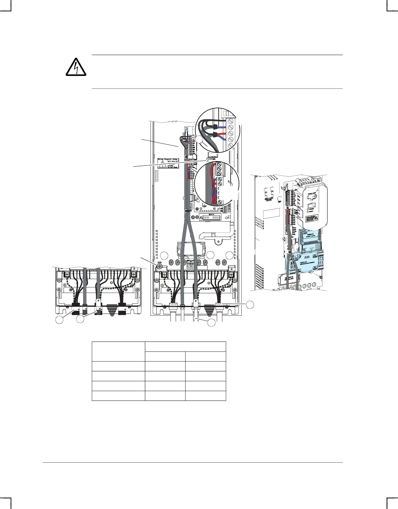
Power wiring torque table
Frame size
R3
lb-ft Nm
T1/U, T2/V, T3/W 2.6 3.5
L1, L2, L3 2.6 3.5
R+, R- 2.6 3.5
PE Ground 1.1 1.5
BREAKERSINPUT
PE
MOTOR
R-
R+
UDC+
W/3TV/2TU/1T3L2L1L
BREAKERSINPUT
PE
MOTOR
R-
R+
UDC+
W/3TV/2TU/1T3L2L1L
R3
Typical Type 1
12
VAR
Power (Green) and
Fault (Red) LEDs
1
8
8
1
Option Mounting
Digital
Inputs
Analog Inputs
and Outputs
6
7
5
EMC
ACH580_Inst_Op_Maint_Rev G.book Page 34