38 ACH580 Installation, Operation and Maintenance Manual
ACH580-01 Installation
12. Strip and connect the individual control wires to the drive terminals. Tighten the
screws to 0.4 lb-ft (0.5…0.6 Nm).
WARNING! To avoid danger or damage to the drive on IT systems and corner
grounded TN systems, see section Drive compatibility for various electrical power
systems on page 16.
Note: UDC+ and UDC- terminals are used for external brake chopper units.
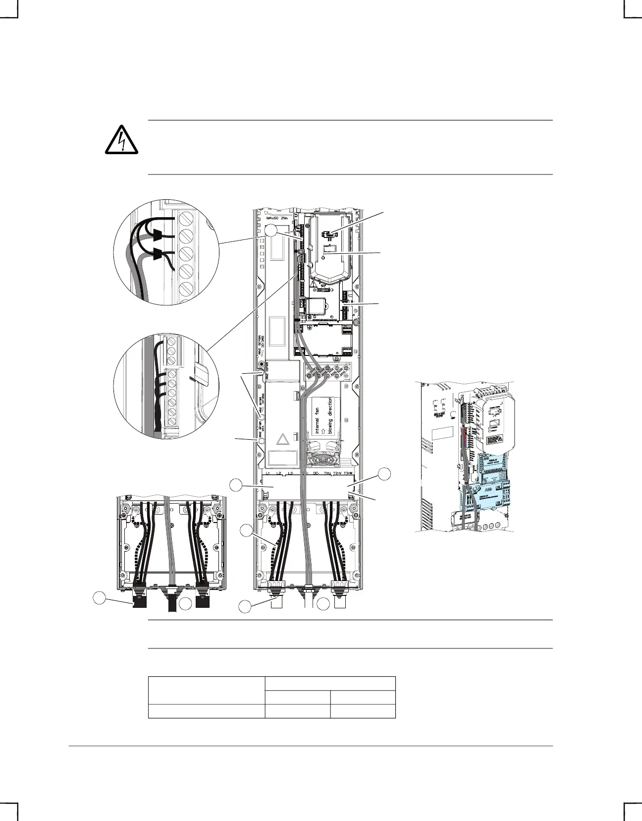
Power wiring torque table
Frame size
R5
lb-ft Nm
T1/U, T2/V, T3/W 4.1 5.6
R5
8
12
6
3
5
1
Panel Connector
Shroud
VAR
EMC
Power (Green) and
Fault (Red) LEDs
Relay
Digital Inputs
Analog Inputs
and Outputs
Typical Type 1
Outputs
1
8
Option Mounting
ACH580_Inst_Op_Maint_Rev G.book Page 38