40 ACH580 Installation, Operation and Maintenance Manual
ACH580-01 Installation
WARNING! To avoid danger or damage to the drive on IT systems and corner
grounded TN systems, see section Drive compatibility for various electrical power
systems on page 16.
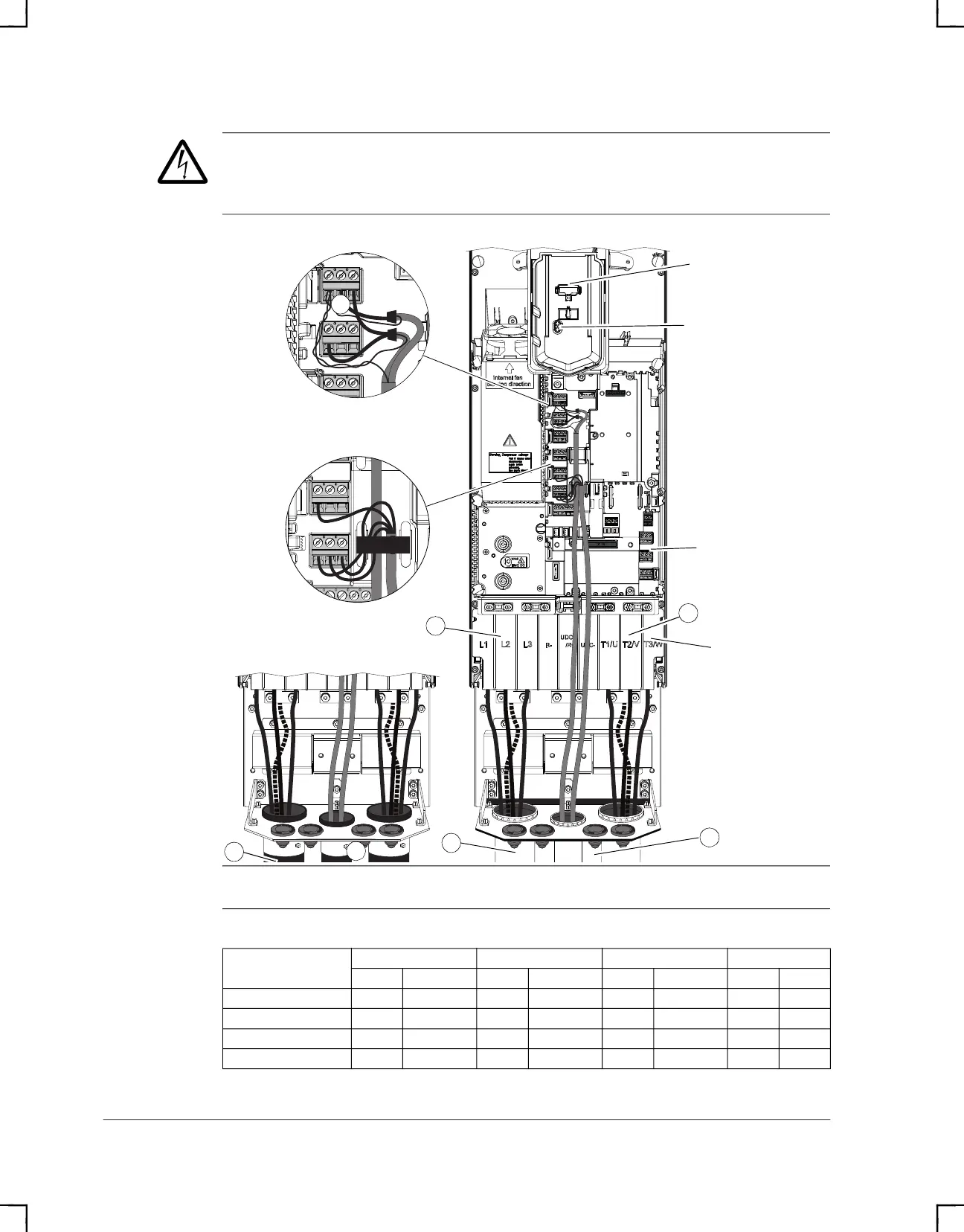
Note: UDC+ and UDC- terminals are used for external brake chopper units.
Power wiring torque table
Frame size
R6 R7 R8 R9
lb-ft Nm lb-ft Nm lb-ft Nm lb-ft Nm
T1/U, T2/V, T3/W 22.1 30 29.5 40 29.6 40 51.6 70
L1, L2, L3 22.1 30 29.5 40 29.6 40 51.6 70
UDC+ and UDC- 22.1 30 29.5 30 29.5 40 51.6 70
PE Ground 7.2 9.8 7.2 9.8 7.2 9.8 7.2 9.8
R7
13
6
Shroud
5
1
Panel Connector
Power (Green) and
Fault (Red) LEDs
Relay Outputs
Digital Inputs
Analog Inputs and Outputs
Typical Type 1
1
9
9
ACH580_Inst_Op_Maint_Rev G.book Page 40