65
3004 MOTOR THERM PROT
Motor overtemperature function. This parameter defines the operation of the
motor thermal protection function which protects the motor from overheating.
0 =
NOT SEL
1 = FAULT
Displays a warning indication at the warning level (97.5 % of the nominal value).
Displays a fault indication when the motor temperature reaches the 100 % level.
The ACS140 coasts to stop.
2 =
WARNING
A warning indication is displayed when the motor temperature reaches the
warning level (95 % of the nominal value).
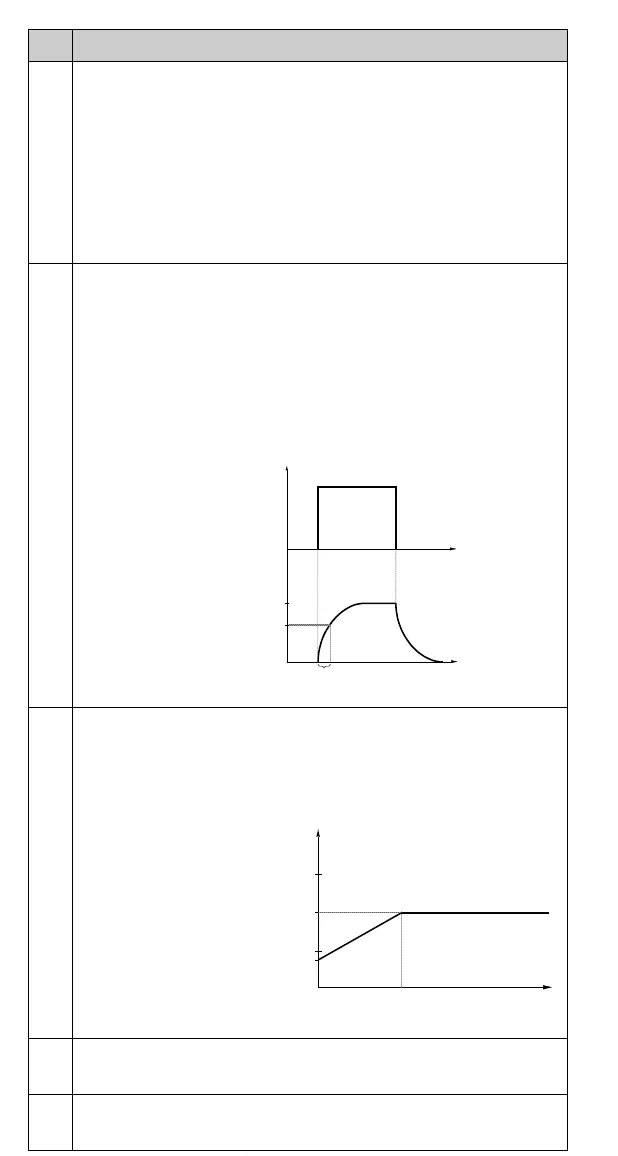
3005 MOT THERM TIME
Time for 63 % temperature rise.This is the time within which the motor
temperature reaches 63 % of the final temperature rise. Figure 9 shows motor
thermal time definition.
If thermal protection according to UL requirements for NEMA class motors is
desired, use this rule of thumb -
MOTOR THERM TIME equals 35 times t6 (t6 in
seconds is the time that the motor can safely operate at six times its rated
current, given by the motor manufacturer). The thermal time for a Class 10 trip
curve is 350 s, for a Class 20 trip curve 700 s and for a Class 30 trip curve
1050 s.
Figure 9 Motor thermal time.
3006 MOT LOAD CURVE
Motor current maximum limit.
MOTOR LOAD CURVE sets the maximum allowable
operating load of the motor. When set to 100 %, the maximum allowable load is
equal to the value of Start-up Data parameter 9906
MOTOR NOM CURRENT. The
load curve level should be adjusted if the ambient temperature differs from the
nominal value.
Figure 10 Motor load curve.
3007 ZERO SPEED LOAD
This parameter defines the maximum allowable current at zero speed relative to
9906
MOTOR NOM CURR. Refer to Figure 10.
3008 BREAK POINT
Break point of motor load curve. Refer to Figure 10 for an example of a motor
load curve. See Figure 12.
Code Description
Motor
Load
100 %
Temp.
Rise
63 %
Mot therm time
t
t
50
100
150
3007 ZERO SPEED LOAD
3006 MOT LOAD CURVE
Output current (%) relative
3008 BREAK POINT Frequency
to 9906 MOTOR NOM CURR
www.barghmaher.org