87
At the motor end the motor cable screen must be earthed 360 degrees with
an EMC cable gland (e.g. ZEMREX SCG Screened cable glands) or the
screen wires must be twisted together into a bundle not longer than five
times its width and connected to the PE terminal of the motor.
Control Cables
Control cables must be multi-core cables with a braided copper wire screen.
The screen must be twisted together into a bundle not longer than five times
its width and connected to terminal X1:1.
Route the control cables as far away as possible from the mains and motor
cables (at least 20 cm). Where control cables must cross power cables
make sure they are at an angle as near 90 degrees as possible. Also the
cable routing must be done so that the distance from the sides of the
converter is at least 20 cm to avoid excessive radiation to the cable.
A double shielded twisted pair cable is recommended for the analogue
signals. Employ one individually shielded pair for each signal. Do not use
common return for different analogue signals.
A double shielded cable is the best alternative for low voltage digital signals
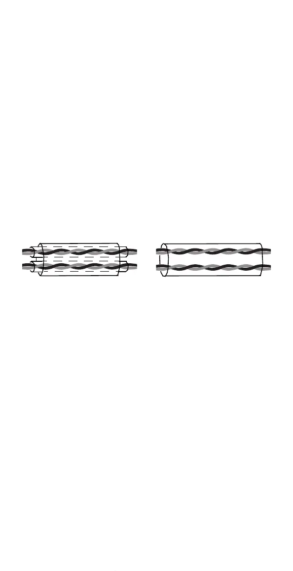
but single shielded twisted multipair cable is also usable (see Figure 22).
Figure 22 A double shielded twisted pair cable on the left and a single
shielded twisted multipair cable on the right.
The analogue and digital input signals should be run in separate, screened
cables.
Relay-controlled signals, providing their voltage does not exceed 48 V, can
be run in the same cables as digital input signals. It is recommended that the
relay-controlled signals be run as twisted pairs.
Never mix 24 VDC and 115/230 VAC signals in the same cable.
Note! When the overriding control equipment and the ACS140 are installed
inside the same cabinet, these recommendations might be overly cautious. If
the customer plans to test the entire installation, there is an opportunity to
save some costs by relaxing these recommendations, for example by using
unshielded cable for the digital inputs. But the customer must verify this.
Control Panel Cable
If the control panel is connected to the converter with a cable, use only the
cable provided with the option package PEC-98-0008. Follow the
instructions delivered with the option package.
Route the control panel cable as far away as possible from the mains and
motor cables (at least 20 cm). Also the cable routing must be done so that
the distance from the sides of the converter is at least 20 cm to avoid
excessive radiation to the cable.
www.barghmaher.org