22 Actual signals and parameters
2007 MINIMUM
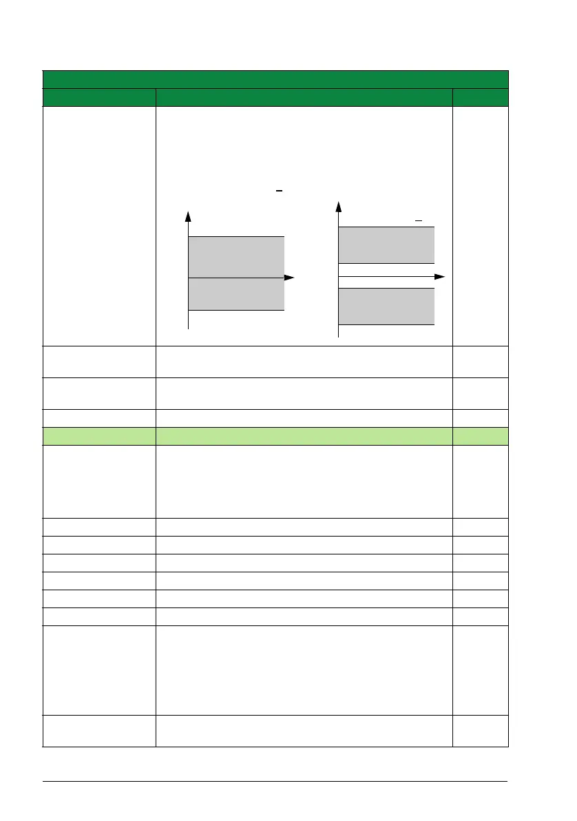
FREQ
Defines the minimum limit for the drive output frequency.
A positive (or zero) minimum frequency value defines two
ranges, one positive and one negative.
A negative minimum frequency value defines one speed
range.
Note: MINIMUM FREQ <
MAXIMUM FREQ.
0.0 Hz
-1400.0
…1400.0 Hz
Minimum frequency 1 = 0.1 Hz
2008 MAXIMUM
FREQ
Defines the maximum limit for the drive output frequency. E: 50.0 Hz
U: 60.0 Hz
0.0…1400.0 Hz Maximum frequency 1 = 0.1 Hz
22 ACCEL/DECEL Acceleration and deceleration times
2201 ACC/DEC 1/2
SEL
Defines the source from which the drive reads the signal
that selects between the two ramp pairs,
acceleration/deceleration pair 1 and 2.
Ramp pair 1 is defined by parameters 2202…2204.
Ramp pair 2 is defined by parameters 2205…2207.
DI5
NOT SEL Ramp pair 1 is used. 0
DI1 Digital input DI1. 1 = ramp pair 2, 0 = ramp pair 1. 1
DI2 See selection DI1.2
DI3 See selection DI1.3
DI4 See selection DI1.4
DI5 See selection DI1.5
COMM Fieldbus interface as the source for ramp pair 1/2 selection,
ie Control word 0301 FB CMD WORD 1 bit 10. The Control
word is sent by the fieldbus controller through the fieldbus
adapter or embedded fieldbus (Modbus) to the drive. For
the Control word bits.
Note: This setting applies only for the DCU profile.
7
SEQ PROG Sequence programming ramp defined by parameter 8422
ST1 RAMP (or 8423/…/8492)
10
All parameters
No. Name/Value Description Def/FbEq
2008
2007
0
f
2008
value is < 0
2007 value is > 0
f
2008
2007
0
-(2007)
-(2008)
t
t
Allowed
frequency range
Allowed
frequency range
Allowed
frequency range
 Loading...


