74 Electrical installation
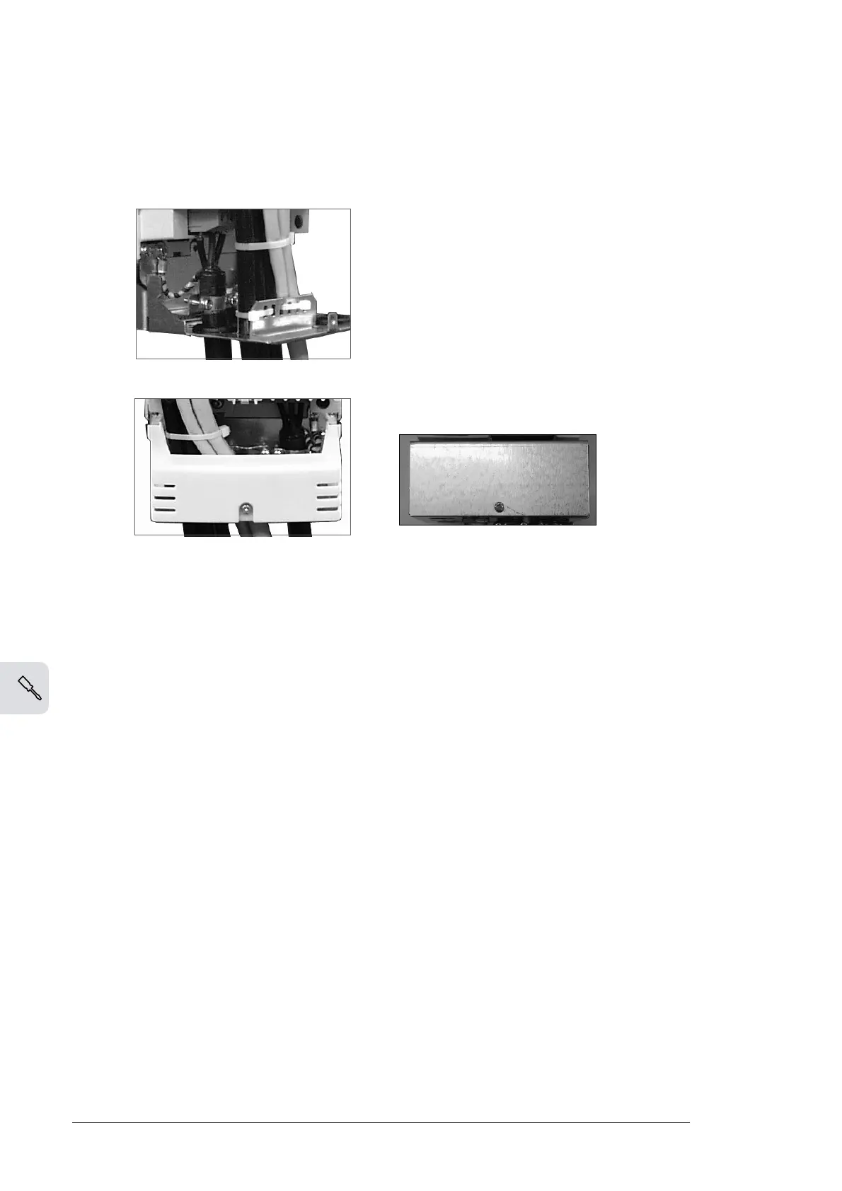
Attaching the control cables and covers
When all control cables are connected, attach them together with cable ties. Units
with a connection box: Attach the cables to the entry plate with cable ties. Units with
a gland box: tighten the clamping nuts of the cable glands.
Attach the connection box cover.
Replace the front cover.
Installation of option modules and PC
Option modules (such as fieldbus adapter, I/O extension module and the pulse
encoder interface) are inserted in the option module slots of the RMIO board (see
Connecting the control cables
on page 70) and fixed with two screws
.
See the
appropriate option module manual for cable connections.
Fiber-optic link
A DDCS fiber-optic link is provided via the RDCO option module for PC tools,
master/follower link and the AIMA-01 I/O module adapter. See
RDCO-01/02/03/04
DDCS communication option modules
(page 173) for the connections. Observe
coloring codes when installing fiber-optic cables. Blue connectors go to blue
terminals, and gray connectors to gray terminals.