42 Planning the electrical installation
Note 7:
Resistor braking of the drive
When the drive is in braking mode for a large part of its operation time, the
intermediate circuit DC voltage of the drive increases, the effect being similar to
increasing the supply voltage by up to 20 percent. Consider the voltage increase
when you determine the motor insulation requirement.
Example: Motor insulation requirement for a 400 V application must be selected as if
the drive were supplied with 480 V.
Note 8:
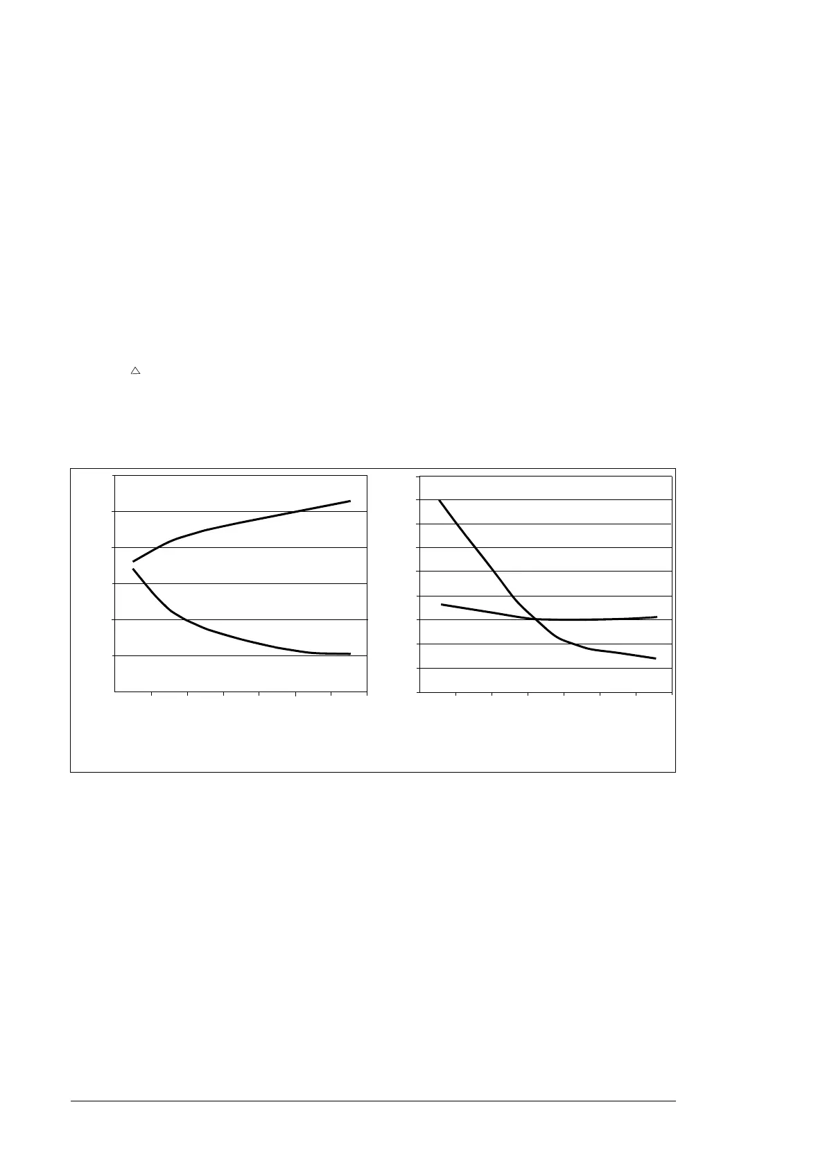
Calculating the rise time and the peak line-to-line voltage
The peak line-to-line voltage at the motor terminals generated by the drive as well as
the voltage rise time depend on the cable length. The requirements for the motor
insulation system given in the table are “worst case” requirements covering
installations with 30 meter and longer cables. The rise time can be calculated as
follows: t = 0.8 ·
Û
LL
/(d
u
/d
t
). Read
Û
LL
and d
u
/d
t
from the diagrams below.
M
ultiply
the values of the graph by the supply voltage
(
U
N
)
. In case of drives with an
IGBT supply unit or resistor braking, the
Û
LL
and d
u
/d
t
values are approximately
20 % higher.
Note 9: Sine filters protect the motor insulation system. Therefore, d
u
/d
t
filter can
be replaced with a sine filter. The peak phase-to-phase voltage with the sine filter is
approximately 1.5 ×
U
N
.
Note 10: Common mode filter is available as a separate option.
Permanent magnet motor
You can connect only one permanent magnet motor to the inverter output.
ABB recommends a safety switch between the permanent magnet motor and the
drive output. The switch isolates the motor during maintenance work.
Û
LL
/U
N
Without du/dt Filter
Cable length (m)
du/dt
U
N
-------------(1/s)
1.0
2.0
5.0
4.0
3.0
1.5
2.5
3.5
4.5
100 200 300
100 200 300
0.0
0.5
1.0
1.5
2.0
2.5
3.0
Cable length (m)
With du/dt Filter
du/dt
U
N
-------------(1/s)
Û
LL
/U
N
5.5