Electrical installation
86
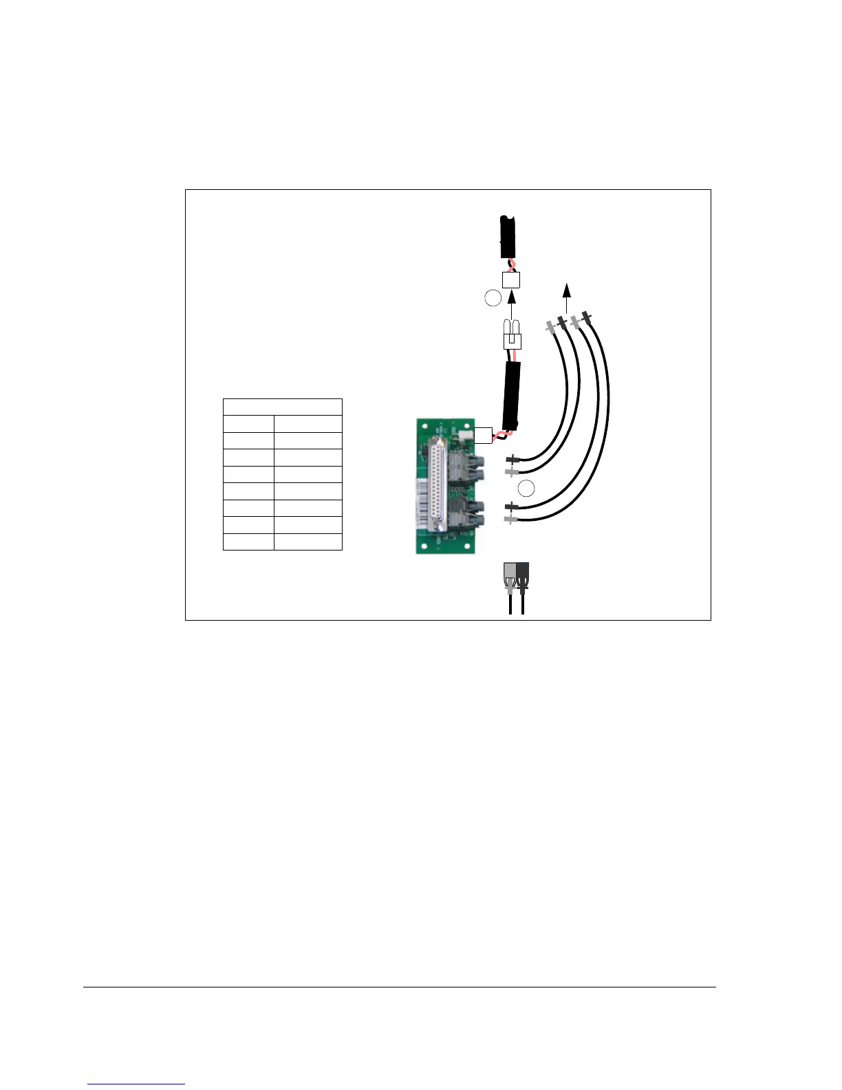
2. Insert the fiber optic cables to the JRIB board terminals.
3. Connect the power supply cable coming from the drive module to the cable
connected to the JRIB board terminals.
Connecting the control cables
See sections Default I/O connection diagram and Control cable connection
procedure below.
TXD = transmitter RXD = receiver
3
Connection table
APOW JRIB
X3: 1 X202: 1
X3: 2 X202: 2
JINT JRIB
V1 V1
V2 V2
V6 V6
V7 V7
JRIB board
V6
V7
V1
V2
1
2
APOW board
2
JINT board

 Loading...


