Electrical installation
87
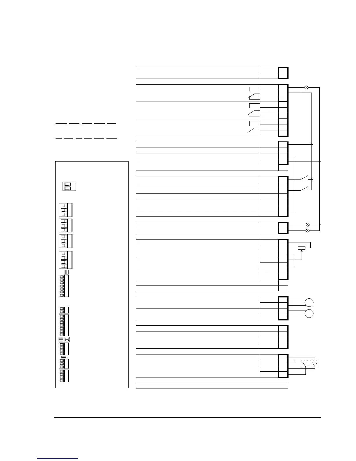
Default I/O connection diagram
Notes:
[…] denotes default setting with ACS850
standard control program (Factory macro).
See Firmware Manual for other macros.
*Total maximum current: 200 mA
The wiring shown is for demonstrative
purposes only. Further information of the
usage of the connectors and jumpers are
given in the text; see also the chapter
Technical data.
Wire sizes and tightening torques:
X
POW, XRO1, XRO2, XRO3, XD24:
0.5 … 2.5 mm
2
(24…12 AWG). Torque:
0.5 N·m (5 lbf·in)
XDI
, XDIO, XAI, XAO, XD2D, XSTO:
0.5 … 1.5 mm
2
(28…14 AWG). Torque:
0.3 N·m (3 lbf·in)
XPOW
External power input
24 V DC, 1.6 A
+24VI 1
GND 2
XRO1, XRO2, XRO3
Relay output RO1 [Ready]
250 V AC / 30 V DC
2 A
NO 1
COM 2
NC 3
Relay output RO2 [Modulating]
250 V AC / 30 V DC
2 A
NO 4
COM 5
NC 6
Relay output RO3 [Fault(-1)]
250 V AC / 30 V DC
2 A
NO 7
COM 8
NC 9
XD24
+24 V DC* +24VD 1
Digital input ground DIGND 2
+24 V DC* +24VD 3
Digital input/output ground DIOGND 4
Ground selection jumper AI1
XDI
Digital input DI1 [Stop/Start] DI1 1
Digital input DI2 DI2 2
Digital input DI3 [Reset] DI3 3
Digital input DI4 DI4 4
Digital input DI5 DI5 5
Digital input DI6 or thermistor input DI6 6
Start interlock (0 = Stop) DIIL A
XDIO
Digital input/output DIO1 [Output: Ready] DIO1 1
Digital input/output DIO2 [Output: Running] DIO2 2
XAI
Reference voltage (+) +VREF 1
Reference voltage (–) -VREF 2
Ground AGND 3
Analog input AI1 (Current or voltage, selectable by jumper AI1) [Speed
reference 1]
AI1+ 4
AI1- 5
Analog input AI2 (Current or voltage, selectable by jumper AI2)
AI2+ 6
AI2- 7
AI1 current/voltage selection jumper AI1
AI2 current/voltage selection jumper AI2
XAO
Analog output AO1 [Current %]
AO1+ 1
AO1- 2
Analog output AO2 [Speed %]
AO2+ 3
AO2- 4
XD2D
Drive-to-drive link termination jumper T
Drive-to-drive link.
B1
A2
BGND 3
XSTO
Safe Torque Off. Both circuits must be closed for the drive to start.
OUT1 1
OUT2 2
IN1 3
IN2 4
Control panel connection
Memory unit connection
XPOW
(2-pole, 2.5 mm
2
)
Order of terminal headers and
jumpers
XRO1
(3-pole, 2.5 mm
2
)
XRO2
(3-pole, 2.5 mm
2
)
XRO3
(3-pole, 2.5 mm
2
)
XD24
(4-pole, 2.5 mm
2
)
XDI
(7-pole, 1.5 mm
2
)
DI/DIO grounding selection
XDIO
(2-pole, 1.5 mm
2
)
XAI
(7-pole, 1.5 mm
2
)
AI1, AI2
XAO
(4-pole, 1.5 mm
2
)
XD2D
(3-pole, 1.5 mm
2
)
XSTO (orange)
(4-pole, 1.5 mm
2
)
T

 Loading...


