10
…4 MECHANICAL INSTALLATION
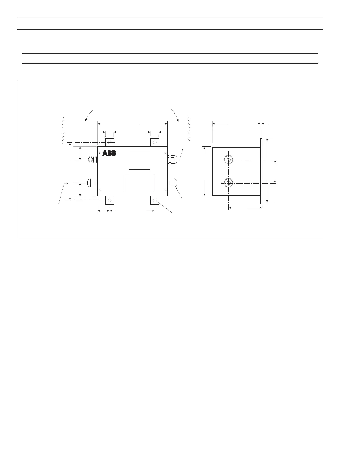
140 (5.5) Centers
110 (4.33) Centers
170 (6.7) 111 (4.37)
120 (4.72)
All Holes Ø7.0 (0.28)
160 (6.3)
83
20 (0.79)
30
(1.18)
60 (2.36)
Centers
Ensure a clearance of at least 100 (4) at
both ends of the unit for acces to the cable
glands and to minimize cable bends.
Mains Cable
Entry (Gray)
Not Used
(Gray)
Output to
Katharometer
3.0 (0.12)
20 (0.79)
30
(1.18)
30
(1.18)
(Blue)
4.1.3 Model 4234 Power Supply Unit – Fig. 4.3
Refer also to IM/4234500 for further details.
Note. The unit must be located in the safe area of the application plant in a sheltered interior environment.
The power supply unit has four fixing lugs for mounting on a suitable vertical surface. The installation dimensions are shown in Fig. 4.3.
Fig. 4.3 Installation Dimensions – Model 4234 Power Supply Unit
Dimensions in mm (in.)