Safe Area
See Note 9
See Note 1
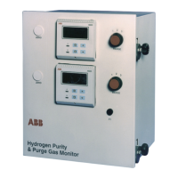
Note 1 Apparatus which is unspecified except that it must not be supplied from nor contain in normal
or abnormal conditions a source of potential with respect to earth in excess of 250 volts r.m.s
or 250 volts d.c.
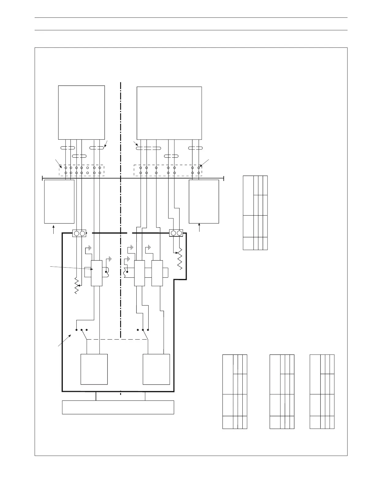
Note 2a The capacitance and either the inductance or the inductance to resistance (L/R) ratio of the
cable connected between the + and – terminals of the power supply Type 4234500/501 and
terminals 1 and 4 of a katharometer Type 0065XX must not exceed the following values:
Hazardous Area
See Notes 2 & 3 for cable details
2
3
1
4
2
3
1
4
2
3
1
4
TB5
18
17
TB6
19
20
POWER SUPPLY
TYPE 4234 500/501
CERTIFIED [Ex ia Ga] IIC
(–20°C ≤ Ta ≤ +55°C)
CERTIFICATE No
BAS 01 ATEX 7041
-
+
2
1
3
2
1
3
RS1
RS2
B1
B2
B3
Gas Monitor Type 6553
–
+
Indicator
eg 4689
I1
–
+
Indicator
eg 4689
I2
4 –
1+
9
10
3 –
2+
KATHAROMETER
TYPE 0065XXX
CERTIFIED Ex ia IIC T4 Ga
CERTIFICATE No
BAS 01 ATEX 1042
3 –
2+
10
4 –
1+
6 –
9
KATHARO
METER
TYPE 0065XXX
CERTIFIED Ex ia IIC T4 Ga
(–20ºC ≤ Ta ≤ +55ºC)
(–20ºC ≤ Ta ≤ +55ºC)
CERTIFICATE No
BAS 01 ATEX 1042
Junction boxes (if required) see note 6.
Location: Hazardous Area or Safe Area
See Note 1
See Note 1
Junction boxes (if required) see note 6.
Location: Hazardous or Safe Area
RV1
RV2
Group
Capacitance
in μF
Inductance
in mH
L/R ratio
in μH/Ohm
IIC
IIB
IIA
7.63
113
999
0.05
0.14
0.37
22
88
177
or
Group
Capacitance
in μF
Inductance
in mH
L/R ratio
in μH/Ohm
IIC
IIB
IIA
38
999
999
0.40
1.20
3.20
75
225
600
or
Group
Capacitance
in μF
Inductance
in mH
L/R ratio
in μH/Ohm
IIC
IIB
IIA
40
999
999
0.05
0.16
0.43
52
210
421
or
Group
Capacitance
in μF
Inductance
in mH
L/R ratio
in μH/Ohm
IIC
IIB
IIA
40
999
999
0.37
1.37
3.28
79
316
632
or
Note 2b The capacitance and either the inductance or the inductance to resistance (L/R) ratio of the cables
connected between (a) terminals 17 & 18 of the gas monitor type 6553 and terminals 9 & 10
of a katharometer Type 0065XX, (b) terminals 19 & 20 of the display/control unit and terminals 9 & 10
of a katharometer Type 0065XX.
Note 2c The capacitance and either the inductance or the inductance to resistance (L/R) ratio of the cables
connected between 3 & 4 of barrier B2 plus terminal 4 of barrier B3 of gas monitor type 6553
and terminals 2, 3 & 6 of a katharometer Type 0065XX, must not exceed the following values:
See Notes 2 & 3 for cable details
Circuit A
Circuit B (see Note 8)
Note 3 The cable may be separate cables or may be installed as separate cir
Note 2d The capacitance and either the inductance or the inductance to resistance (L/R) ratio of the cables connected
between terminals 3 & 4 of barrier B1 of gas monitor type 6553 and terminals 2 & 3 of Katharometer type 0065XX,
must not exceed the following values:
cuits within a type ‘A’ or a type ‘B’
multicore cable as defined in EN60079 - 14: 2008, 12.2.28 (latest edition) subject to the following:
a. Each circuit shall be individually screened within a type ‘A’ multicore cable.
b. The peak voltage of any other circuit within a type ‘B’ multicore cable must not exceed 60 volts.
Note 4 The installation must comply with national requirements (e.g. within the UK the standard EN60079-14: (latest edition) is used).
Note 5 The system must be marked with a durable label. The label should appear on or adjacent to the principal
item of electrical apparatus in the system or at the interface between the intrinsically safe and non-
intrinsically safe circuits.
This marking shall include the word SYST or SYSTEM, e.g.
‘BAS SYSTEM No Ex 01E2044’ or ‘BAS No Ex 01E2044 SYST’
Note 6 A junction box, if used, must satisfy the requirements of Clauses 6.1 and 6.3.1 of EN60079:11 (latest edition).
Note 7 Circuit A or Circuit B may be omitted.
Note 8 Circuit B may be identical to Circuit A.
Note 9 This item may or may not be fitted.
POWER SUPPLY
TYPE 4234 500/501
CERTIFIED [Ex ia Ga] IIC
(–20°C ≤ Ta ≤ +55°C)
CERTIFICATE No
BAS 01 ATEX 7041
-
+
See Note 10
Note 10 Zener barriers (B1, B2 & B3) MTL 7755ac BAS 01 ATEX 7217 & IECEx BAS 04.0025.
Display/Control Unit
Model 6553
CERTIFIED [Ex ia Ga] IIC
(–20ºC ≤ Ta ≤ +40ºC)
CERT No BAS 01 ATEX 7043
& IECEx BAS 04.0025
2a
2b
2d
2c
2b
2a
I.S. Earth
I.S. Earth
Fig. 5.1 AK101 System Diagram