22
TB1
T1
L N E
F2 F3
Warning. Hazardous Voltages.
There are no servicable parts in this unit.
Return to the manufacturer if faulty or seek
the services of a qualified engineer.
Switch off the mains supply and disconnect
it before removing the cover for any reason.
6
8
10
230
230V
115V
V
115 V
Output Current (mA) Links
350 C to X
250 D to X
180 E to X
NO connections should be made to
points A or B
TB2
–
+
F1
B
A
C
X
D
E
M5 Earth Stud Voltage Links
Cable Gland for
AC Mains Input
(Gray)
Output
Current
Links
Cable Gland
Not Used
(Gray)
Cable Gland for
DC Output to
Katharometer
(Blue)
Mains Input
Terminal Block
DC Output
Terminal Block
Fuses*
*Refer to the 4234 manual for fuse details.
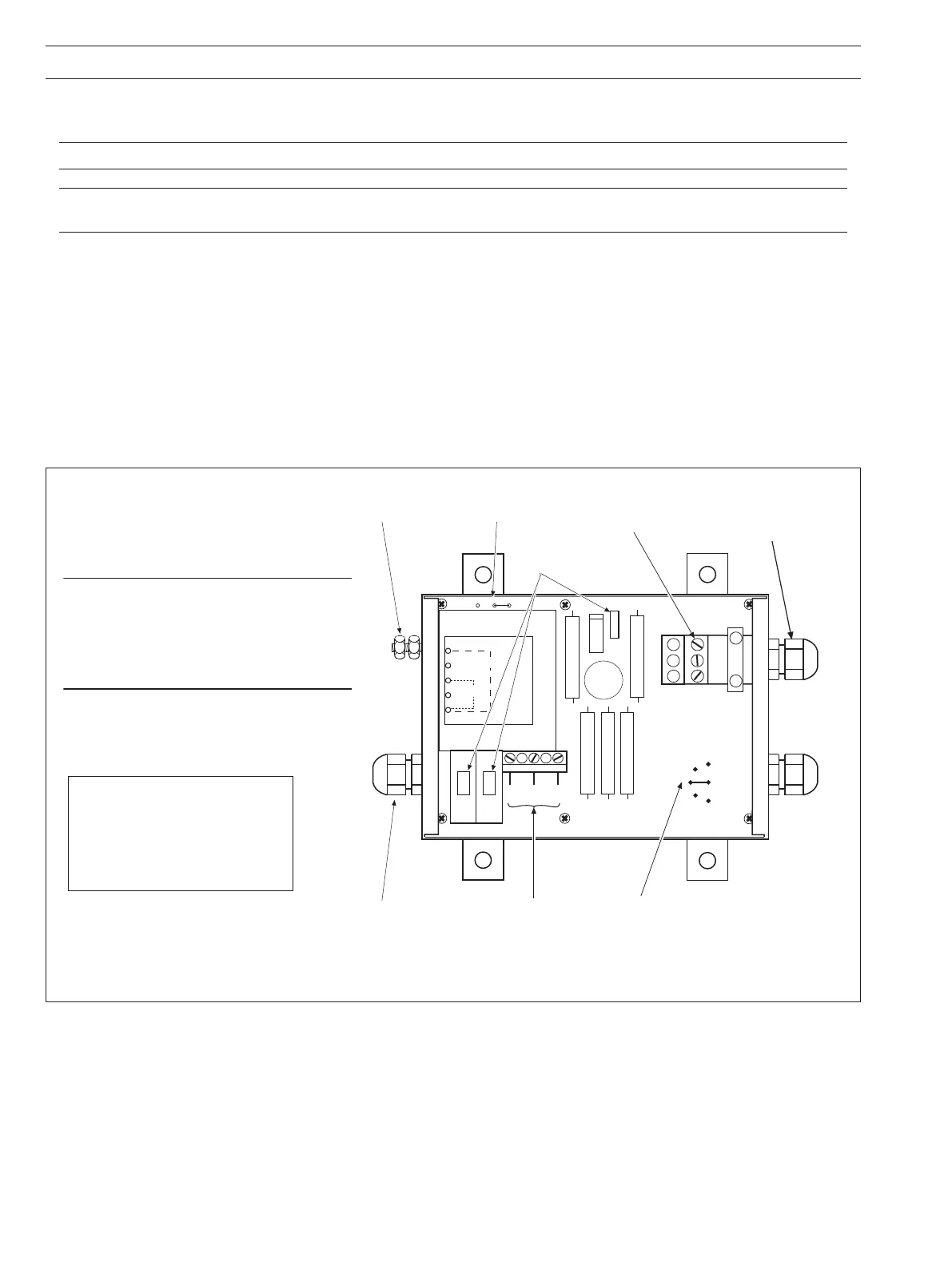
5.1.3 Model 4234 Power Supply Unit – Fig. 5.9
Refer also to IM/4234500 for further details.
Caution. Do NOT connect mains supply to the power supply unit with the output terminals on open circuit.
Note. Ensure that the power supply unit is correct for the mains supply voltage available. A nominal 115V unit cannot be
adapted for use with a nominal 230V supply or vice versa. Check voltage link is set to correct supply voltage – see Fig. 5.9.
Remove the cover of the unit to gain access to the terminal blocks inside.
Identify the terminal block (TB1) adjacent to the transformer T1 and ensure the correct transformer tapping is used for the incoming
mains supply, i.e.
link from tapping 6 to 10 for 230V, or
link from tapping 8 to 10 for 115V.
Make electrical connections in accordance with the information given in the wiring diagrams Figs 5.1 and 5.6 and the cable details
in Section 5.2.1.
The electrical connections are made at terminal blocks TB1 and TB2 through the appropriate cable gland or any replacement gland
to suit intrinsically safe wiring requirements. Secure the incoming cable by the cable clips adjacent to the terminal blocks.
Replace the cover when wiring is complete.
...5 ELECTRICAL INSTALLATION
Fig. 5.9 Location of Components Inside Case – Model 4234 Power Supply Unit