12
4.2 Sample Gas Interconnections
Note. A hazardous mixture of hydrogen-in-air could develop in the event of leakage from the sample gas system.
Katharometer Analyzer panels must be located in a ventilated area.
The sample pressure must not exceed 0.35bar (Gauge) for Model 6540–203 and 10bar (Gauge) for Model 6548–000.
The incoming sample gas temperature must not exceed 55C (131F). Ideally the sample gas temperature should be allowed to reach
ambient temperature before entry to the katharometer unit.
If there is a risk of significant particle contamination incorporate a suitable 1m filter unit in the system before the sample gas enters
the Analyzer system.
Compression couplings are supplied at the sample inlet and outlet to the katharometer panel. These couplings are suitable for
connecting 8mm (0.31 in.) (Model 006540 203) or 6mm (0.24 in.) (Model 006548 000) outside diameter metal tube. It is
recommended that stainless steel tube is used.
The complete tubing system should be tested for leaks in accordance with the requirements of the responsible authority.
…4 MECHANICAL INSTALLATION
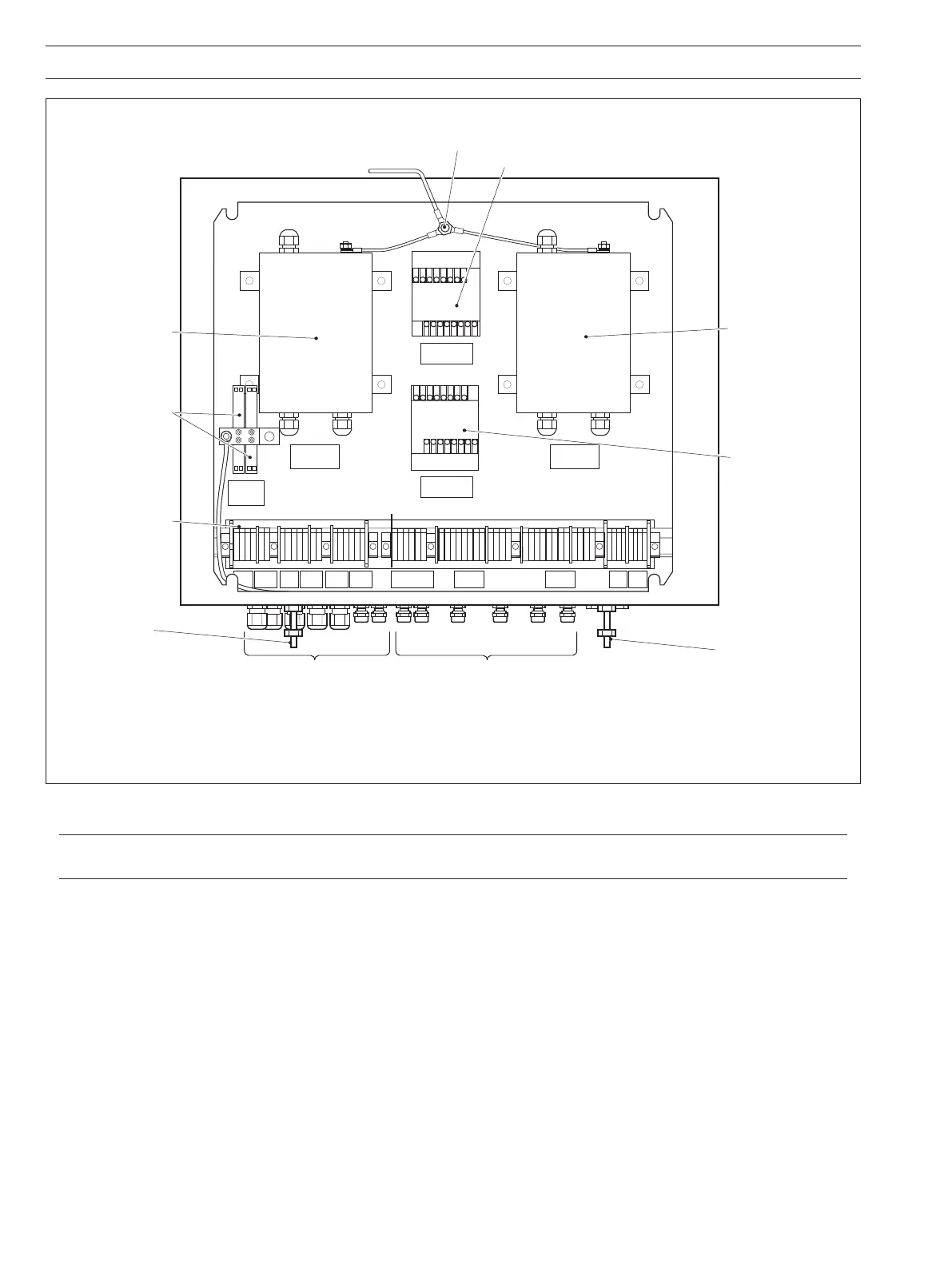
Fig. 4.5 Location of Main Components on Cubicle Backplate
PSU 1 TO
KATH 1
TB18
12 34 56
78 91011 13
12
14 15 16 17 18 19 20 21 22 23 24 25 26 27 28 29 30 31 32 33 34 35 36 37
LN
EE
LN
EE
38 39 40 41 42 43 44 45 46 47 48 49
Note. The number of terminals, cable glands, low-flow alarms, PSU's and zener barriers
(flow alarms) vary according to ordering information details specified.
B6
POWER SUPPLY
UNIT No. 1
B9
LOW FLOW
ALARM RELAY No. 2
B8
LOW FLOW
ALARM RELAY No. 1
No. 1 No. 2
B4 B5
BARRIER FLOW
ALARM
E SCR S1 S2 0V 0V -12V+12V
CH 1
I N COM NC NO
1 2 1 2
3 4 3 4
Low Flow Alarm
Zener Barriers
1 and 2
(if iftted)
(B4 and B5)
12
Low Flow Alarm
Relay 2 (if fitted)
Earth Point (Ground)
(NOT intrinsically safe earth)
Low Flow Alarm
Relay 1 (if fitted)
Cable Glands for Cable
Terminations in
Hazardous Areas
(Blue)
Cable Glands for
Cable Terminations
in Safe Areas
To Cubicle Earth
(NOT intrinsically safe earth)
Power Supply
Unit 2 (if fitted)
Power Supply
Unit 1
B7
POWER SUPPLY
UNIT No. 2
MAINS
SUPPLY
TB7
MAINS
SUPPLY
TB6
TB10
ALARM AND
RETRANS 2
TB11
ALARM AND
RETRANS 1
No1 No2
TB12
O/P FLOW ALARMS
TB13
LOW FLOW
ALARM 2
TB14
LOW FLOW
ALARM 1
PSU 2 TO
KATH 2
TB15
PSU 1 TO
KATH 1
TB17
PSU 2 TO
KATH 2
TB16
Terminal Block
Intrinsically
Safe Earth
System Safety Earth