AO2000-LS25 LASER ANALYZERS | OI/AO2000-LS25-EN REV. D 11
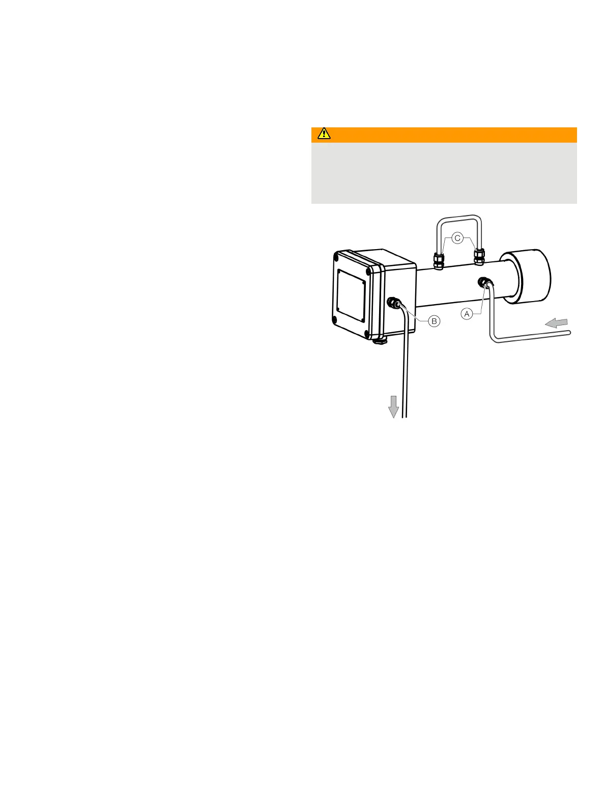
• The purge gas inlet must be connected to the Swagelok®
fitting
A on the receiver unit. Keep gland C closest to the
connection flange free.
• The flow direction of the purge gas must be designed
according to Figure 1 on page 7.
• The electrical inputs/outputs of the device must be routed
via a suitable interface relay. The interface relay is controlled
by the purging and monitoring unit and disconnects the
inputs / outputs on all poles in the event of a fault.
• The operating instructions of the purging and monitoring
unit as well as other components of the pressurized
enclosure must be observed during installation.
• The customer must check and, if necessary, set the process-
specific purge parameters (see Purge parameters for
pressurized enclosure on page 10) in the purging and
monitoring unit during commissioning.
Pressurized enclosure with nitrogen N
2
Risk of suffocation
Risk of suffocation in the event of uncontrolled escaping
nitrogen.
• Ensure that all purge gas lines are tight and that the purge
gas emerges into the outside air in a controlled fashion.
Purge gas entry from the transmitter unit
Purge gas entry to the purging and monitoring unit
Jumper connections
Figure 3: Purge gas connection to the receiver unit (N
2
as purge gas)
If nitrogen purging is required for the measurement (e.g. in high-
temperature applications or small O
2
/ H
2
O measuring ranges),
the purge gas connection must be as shown in Figure 3. The
connection of the transmitter unit is unchanged.