12 AO2000-LS25 LASER ANALYZERS | OI/AO2000-LS25-EN REV. D
… 2 Use in potentially explosive atmospheres in accordance with ATEX and IECEx
… Use in ATEX / IECEx Zone 1
Housing purge control flow
The power supply of the gas analyzer is provided via the purging
and monitoring unit of the housing purging.
• The power supply to the gas analyzer may only be released
from the purging and monitoring unit after the successful
initial purge.
• The purging and monitoring unit monitors the overpressure
inside the housing and de-energizes the gas analyzer if the
level is below the minimum overpressure (e.g. due to a
leakage or purge gas supply failure).
Sequence of the purging and monitoring unit
The gas analyzer is powered from the purging and monitoring
unit, i.e. the purging and monitoring unit prevents the gas
analyzer from being energized before the purge is completed.
The flow sequence of the purging and monitoring unit is as
follows:
1. After the start of the sequence, the purge gas flow and
overpressure in the monitor are monitored by the purging
and monitoring unit.
2. If the minimum flow rate of the purge gas and the
overpressure are within the specified limits (see Purge
parameters for pressurized enclosure on page 10), the
purge timer (initial purge time) can be started;
3. After the initial purge time has elapsed, the power supply
is released for the gas analyzer.
4. In the event of an error in one of the sequence steps, the
controller must be set up to be reset to the beginning.
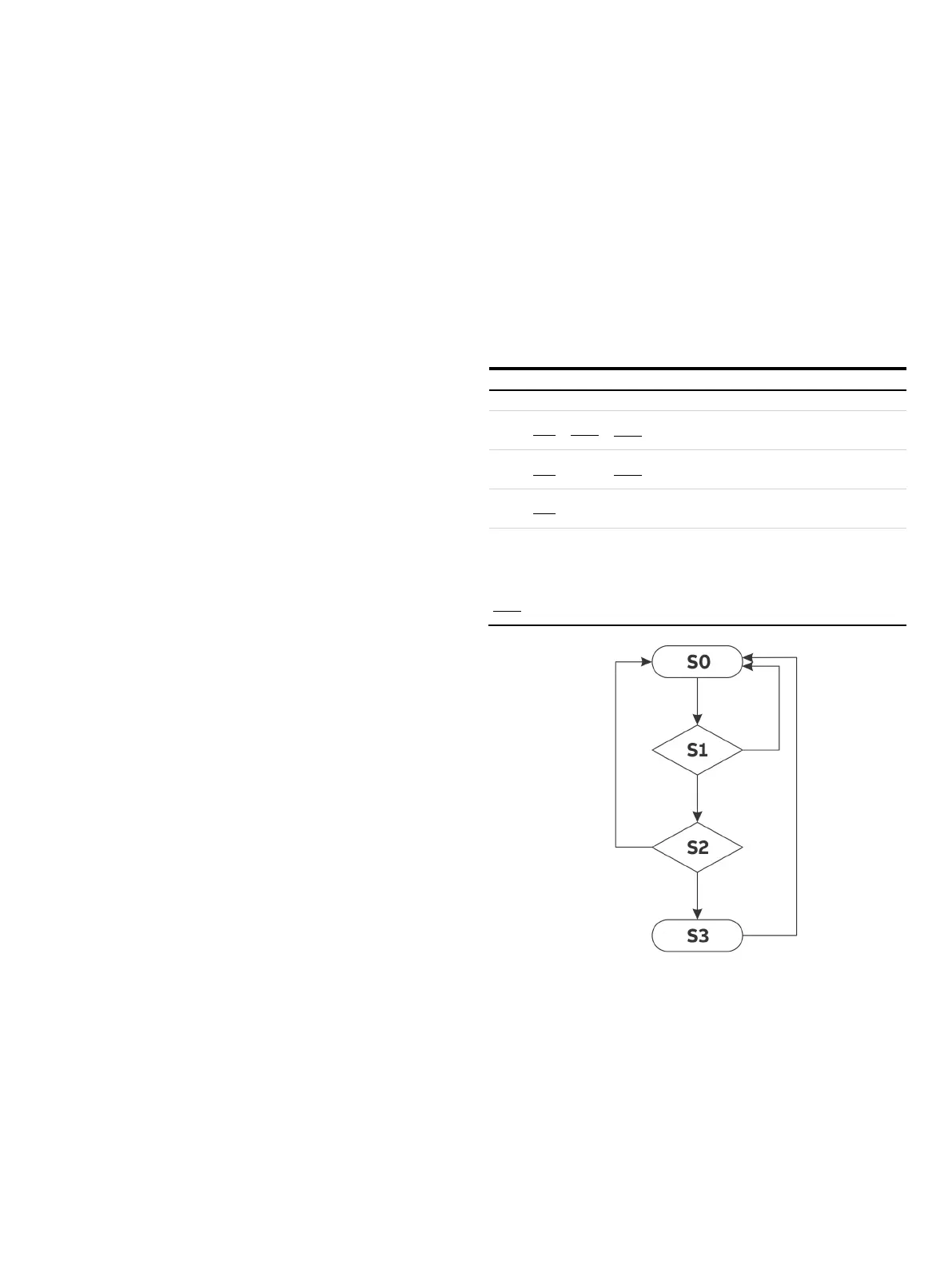
This sequence is presented in Figure 4.
Each state of the system is defined in response to the inputs of
the monitor. The states are unique. Transitions between the
states are only allowed along the paths defined by the arrows
and towards the arrows.
The logical conditions for each state are defined by the following
boolean logical expressions:
Logical expressions of the purging sequence
Conditions for starting the purge
– S1
[
]
&&&
Initial purging in progress
– S2
]
&&
[
]
&
Initial purging completed, power supply released
– S3
]
&&
[
]
]
Exceeds maximum overpressure
]
Gage pressure > minimum
]
Purge flow > minimum
]
Initial purging time completed
Initial purging time incomplete
Figure 4: Status diagram of housing purging